
Page 185 - Marks Calculation for Machine Design
P. 185
P1: Shibu
January 4, 2005
14:25
Brown˙C04
Brown.cls
167
COMBINED LOADINGS
4.5
TORSION AND BENDING
The fourth combination of loadings to be considered is torsion and bending. This is a very
common loading for machine elements. Shown in Fig. 4.16 is a bent solid circular rod being
used as a crank arm. The downward force (P) produces both a torsion and a bending in the
shaft, with the resulting stresses maximized at the cantilevered wall support at point A.
Wall
A
L AB
P
Crank arm B
C Crank axis
L
BC
FIGURE 4.16 Torsion and bending loads.
The force (P) acting at point C on the crank arm produces a bending moment (M B ),or
a torque (T AB ), about the crank axis AB, and is given by Eq. (4.5).
M B = T AB = P × L BC (4.5)
The force (P) also produces a bending moment (M A ) at the wall and is given by Eq. (4.6).
M A = P × L AB (4.6)
A shear force (V ) is developed in the crank arm and is equal to the magnitude of the
applied force (P), that is,
V = P (4.7)
Therefore, stress elements in the cross section of the crank arm at the wall are subjected
to a torque (T AB ), a bending moment (M A ), and a shear force (V ).
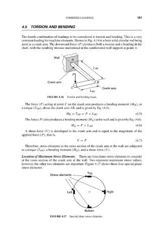
Location of Maximum Stress Elements. There are four plane stress elements to consider
at the cross section of the crank arm at the wall. Two represent maximum stress values;
however, the other two elements are important. Figure 4.17 shows these four special plane
stress elements.
Top
Stress elements
Left Right
Bottom
FIGURE 4.17 Special plane stress elements.