
Page 180 - Marks Calculation for Machine Design
P. 180
P1: Shibu
January 4, 2005
Brown˙C04
Brown.cls
162
U.S. Customary 14:25 STRENGTH OF MACHINES SI/Metric
σ top = σ axial + σ max σ top = σ axial + σ max
= (−0.25 kpsi) + (−2.0 kpsi) = (−1.2MPa) + (−16.0MPa)
=−2.25 kpsi =−17.2MPa
Step 6. Display the answer for the maximum Step 6. Display the answer for the maximum
normal stress at the top (σ top ) found in step 5, normal stress at the top (σ top ) found in step 5,
in kpsi, on a uniaxial stress element. in MPa, on a uniaxial stress element.
0 0
0 0
2.25 2.25 17.2 17.2
0 0
0 0
Negative signs are not used in the above di- Negative signs are not used in the above di-
agram as the directions of the arrows indicate agram as the directions of the arrows indicate
compression. As stated at the end of Example compression. As stated at the end of Example
1, this diagram will be a starting point for the 1, this diagram will be a starting point for the
discussions in Chap. 5. discussions in Chap. 5.
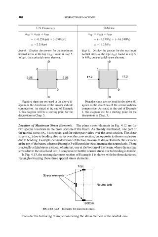
Location of Maximum Stress Elements. The plane stress elements in Fig. 4.12 are for
two special locations in the cross section of the beam. As already mentioned, one part of
the normal stress (σ xx ) is constant and the other part varies over the cross section. The shear
stress (τ xy ) due to bending also varies over the cross section, but opposite to the normal stress
due to bending. Example 2 considered one of the two maximum stress elements, the element
at the top of the beam, whereas Example 3 will consider the element at the neutral axis. There
is actually a third stress element of interest, one at the bottom of the beam, where the normal
stress due to the axial load is still compressive but the normal stress due to bending is tensile.
In Fig. 4.13, the rectangular cross section of Example 1 is shown with the three darkened
rectangles locating these three special stress elements.
Top
Stress elements
Neutral axis
Bottom
FIGURE 4.13 Elements for maximum stress.
Consider the following example concerning the stress element at the neutral axis.