Page 178 - Marks Calculation for Machine Design
P. 178

P1: Shibu
                                      14:25
                          January 4, 2005
        Brown.cls
                 Brown˙C04
                                           STRENGTH OF MACHINES
                  160
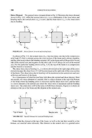
                  Stress Element. The general stress element shown in Fig. 4.2 becomes the stress element
                  shown in Fig. 4.11, where the normal stress (σ xx ) is a combination of the axial stress and
                  bending stress, the normal stress (σ yy ) is zero, and the shear stress (τ xy ) is the shear stress
                  due to bending.
                                s yy                          0
                                  t xy                  t xy
                                                      t
                                      t xy            xy
                                                                           P   My
                    s xx                          s xx                s  = –   + –
                                                                       xx
                                              →                            A   I
                                         s xx
                       t xy                                         t  =  VQ
                                                                    xy
                                                                        Ib
                           t xy                                  t xy
                                 s yy                         0
                    FIGURE 4.11  Stress element for axial and bending loads.
                    As shown in Fig. 4.11, the normal stress (σ xx ) has two terms, one due to the compressive
                  axial load (P) that is constant across the cross section of the beam and is always negative,
                  and the other term is due to the bending moment (M) in the beam and will be positive on one
                  side of the neutral axis and negative on the other side. It will always be zero at the neutral
                  axis. For the particular loading shown in Fig. 4.10, the top of the beam is in compression
                  and the bottom is in tension.
                    The shear stress due to bending (τ xy ) is shown downward on the right edge of the stress
                  element because the shear force (V ) will be downward at the right side of the cross section
                  of the beam. This shear stress due to bending will be maximum at the neutral axis and zero
                  at the top and bottom of the beam.
                    As a consequence of what has just been said about the normal and shear stresses, there
                  are actually two stress elements to consider. One is a stress element at the top or the bottom
                  of the beam where the bending stress is maximum and the shear stress zero; and the other
                  is a stress element at the neutral axis where the shear stress is maximum and the bending
                  stress zero. The axial stress will be the same on both these elements. Figure 4.12 shows an
                  element at the top of the beam and the element at the neutral axis.

                                 0                                0
                                                            t
                           0                                max
                          0                             t max
                                              P   My                           P
                     s                  s  = –   –    s                  s  = –
                      xx
                                         xx
                                              A   I    xx                 xx   A
                                                                            VQ max
                                      0                                t max =
                                                                              Ib
                                    0                                t max
                     Top of beam                      Neutral axis
                                 0                                0
                     FIGURE 4.12  Special elements for axial and bending loads.
                    Notice that the element at the top of the beam, as well as the one that would be at the
                  bottom, are uniaxial stress elements. The element at the neutral axis is a general stress
   173   174   175   176   177   178   179   180   181   182   183