
Page 174 - Marks Calculation for Machine Design
P. 174
P1: Shibu
January 4, 2005
14:25
Brown.cls
Brown˙C04
STRENGTH OF MACHINES
156
interest. As with the uniaxial stress element, the four shear stresses (τ xy ) are zero. In the case
of a thin-walled spherical vessel under internal pressure, the normal stresses (σ sph ) in both
directions are equal. However, for either thin-walled or thick-walled cylinders, the normal
stresseswillbedifferent,andinfactthehooportangential stresswillbetwice theaxialstress.
The radial stress (σ r ) in a thick-walled cylinder acts perpendicular to the plane stress
element, in the z-direction, similar to that for an internal pressure (p i ), so it cannot be
depicted in Fig. 4.4.
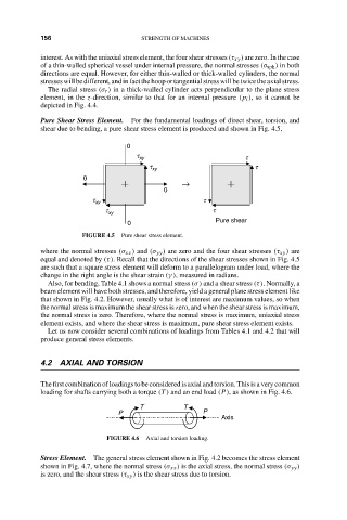
Pure Shear Stress Element. For the fundamental loadings of direct shear, torsion, and
shear due to bending, a pure shear stress element is produced and shown in Fig. 4.5,
0
t xy t
t xy t
0
→
0
t xy t
t xy t
0 Pure shear
FIGURE 4.5 Pure shear stress element.
where the normal stresses (σ xx ) and (σ yy ) are zero and the four shear stresses (τ xy ) are
equal and denoted by (τ). Recall that the directions of the shear stresses shown in Fig. 4.5
are such that a square stress element will deform to a parallelogram under load, where the
change in the right angle is the shear strain (γ ), measured in radians.
Also, for bending, Table 4.1 shows a normal stress (σ) and a shear stress (τ). Normally, a
beam element will have both stresses, and therefore, yield a general plane stress element like
that shown in Fig. 4.2. However, usually what is of interest are maximum values, so when
the normal stress is maximum the shear stress is zero, and when the shear stress is maximum,
the normal stress is zero. Therefore, where the normal stress is maximum, uniaxial stress
element exists, and where the shear stress is maximum, pure shear stress element exists.
Let us now consider several combinations of loadings from Tables 4.1 and 4.2 that will
produce general stress elements.
4.2 AXIAL AND TORSION
Thefirstcombinationofloadingstobeconsideredisaxialandtorsion.Thisisaverycommon
loading for shafts carrying both a torque (T ) and an end load (P), as shown in Fig. 4.6.
T T
P P
Axis
FIGURE 4.6 Axial and torsion loading.
Stress Element. The general stress element shown in Fig. 4.2 becomes the stress element
shown in Fig. 4.7, where the normal stress (σ xx ) is the axial stress, the normal stress (σ yy )
is zero, and the shear stress (τ xy ) is the shear stress due to torsion.