
Page 173 - Marks Calculation for Machine Design
P. 173
P1: Shibu
14:25
January 4, 2005
Brown.cls
Brown˙C04
COMBINED LOADINGS
155
The first subscript on the stresses shown in Fig. 4.2 indicates the direction of the stress,
and the second subscript indicates the direction of the perpendicular to the surface area on
which the stress acts. For the shear stresses shown, (τ xy ) and (τ yx ) are interchangeable, so
only (τ xy ) will be used in the remainder of this book. As mentioned earlier, and as shown in
Fig. 4.2, the internal pressure (p i ) acts perpendicular to the plane stress element; however,
it is directed toward the surface of the element and so it is considered a negative normal
stress. More about the effect of an internal pressure on the overall stress distribution on an
element is presented in Chap. 5.
Although Fig. 4.2 shows the worst case senario for a stress element, and as mentioned ear-
lier a very rare occurrence in actual engineering practice, there are three special plane stress
elements. These three elements are called uniaxial stress element, biaxial stress element,
and pure shear stress element. These three elements have special significance that will be
discussed in Chap. 5.
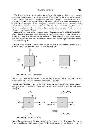
Uniaxial Stress Element. For the fundamental loadings of axial, thermal, and bending, a
uniaxial stress element is produced and shown in Fig. 4.3,
0
0
0
s xx s
s
s xx
←
0
0 Uniaxial
0
FIGURE 4.3 Uniaxial stress element.
where there is only normal stress (σ) along the axis of interest; and the other stresses, the
normal stress (σ yy ) and the four shear stresses (τ xy ), are zero.
Biaxial Stress Element. For the pressure loadings on thin-walled vessels, both spherical
and cylindrical, and thick-walled cylinders, a biaxial stress element is produced and shown
in Fig. 4.4,
s yy s hoop or s t
0
0
s xx
Æ
s xx s axial or s a s axial or s a
0
0
Biaxial
s yy s hoop or s t
FIGURE 4.4 Biaxial stress element.
where there are the normal stresses (σ axial ) or (σ a ) in the x-direction, along the axis of
interest, and the normal stresses (σ hoop ) or (σ t ) in the y-direction, perpendicular to the axis of