
Page 172 - Marks Calculation for Machine Design
P. 172
P1: Shibu
14:25
January 4, 2005
Brown.cls
Brown˙C04
STRENGTH OF MACHINES
154
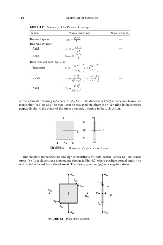
TABLE 4.2
Element Summary of the Pressure Loadings Shear stress (τ)
Normal stress (σ)
p i r m
Thin-wall sphere σ sph = —
2 t
Thin-wall cylinder:
p i r m
Axial σ axial = —
2 t
p i r m
Hoop σ hoop = —
t
Thick-wall cylinder: (p o = 0)
p i r 2 2
Tangential σ t = i 1 + r o —
r − r 2 i r
2
o
p i r 2 r o 2
Radial σ r = i 1 − —
2
r − r i 2 r
o
p i r 2
Axial σ a = i —
2
r − r 2 i
o
of the element, meaning ( x z) or ( y z). The dimension ( z) is very much smaller
than either ( x) or ( y) so that it can be assumed that there is no variation in the stresses
perpendicular to the plane of the stress element, meaning in the z direction.
y y
∆y z
x
∆z
∆x
FIGURE 4.1 Geometry of a plane stress element.
The standard nomenclature and sign conventions for both normal stress (σ) and shear
stress (τ) for a plane stress element are shown in Fig. 4.2, where positive normal stress (σ)
is directed outward from the element. Therefore, pressure (p i ) is a negative stress.
s yy s yy
t xy
t xy •
t yx t yx
s xx
s xx •
s xx p i
t yx
t xy ×
t xy
s yy s yy
FIGURE 4.2 Plane stress element.