Page 183 - Marks Calculation for Machine Design
P. 183

P1: Shibu
                          January 4, 2005
                                      14:25
                 Brown˙C04
        Brown.cls
                                            COMBINED LOADINGS
                      The thermal stress due to a temperature drop ( T ) is given by Eq. (4.6) where the thermal
                    strain (ε T ) is multiplied by the modulus of elasticity (E)  165
                                          σ thermal = Eε T = Eα( T )             (4.2)
                    and (α) is the coefficient of thermal expansion of the pipe.
                      Combining these two normal stresses, both of which are constant over the cross section
                    of the pipe, gives the single stress (σ xx ) shown in Eq. (4.3),
                                                                 L

                             σ xx = σ axial + σ thermal = Eε axial + Eε T = E  + α( T )  (4.3)
                                                                 L
                    where
                                             L    L installed − L o
                                                =                                (4.4)
                                             L        L o
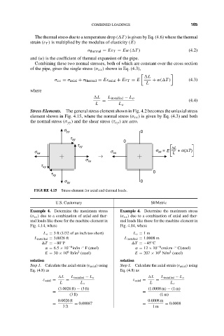
                    Stress Elements. The general stress element shown in Fig. 4.2 becomes the uniaxial stress
                    element shown in Fig. 4.15, where the normal stress (σ xx ) is given by Eq. (4.3) and both
                    the normal stress (σ yy ) and the shear stress (τ xy ) are zero.
                                 s yy                         0
                                   t xy
                                                        0
                                      t xy                                ∆L
                      s xx                         s xx             s  = E  L  +  a(∆T)
                                                                     xx
                                              →
                                         s xx
                        t xy
                                                                   0
                            t xy
                                 s yy                         0
                     FIGURE 4.15  Stress element for axial and thermal loads.

                              U.S. Customary                      SI/Metric
                    Example 4. Determine the maximum stress  Example 4. Determine the maximum stress
                    (σ xx ) due to a combination of axial and ther-  (σ xx ) due to a combination of axial and ther-
                    mal loads like those for the machine element in  mal loads like those for the machine element in
                    Fig. 4.14, where                   Fig. 4.14, where
                         L o = 3 ft (1/32 of an inch too short)  L o = 1m
                      L installed = 3.0026 ft           L installed = 1.0008 m
                                                                  ◦
                         T =−80 F                           T =−45 C
                                ◦
                                        ◦
                                                                            ◦
                          α = 6.5 × 10 −6 in/in · F (steel)  α = 12 × 10 −6 cm/cm · C(steel)
                                                                      9
                                  6
                                      2
                                                                          2
                          E = 30 × 10 lb/in (steel)         E = 207 × 10 N/m (steel)
                    solution                           solution
                    Step 1. Calculate the axial strain (ε axial ) using  Step 1. Calculate the axial strain (ε axial ) using
                    Eq. (4.8) as                       Eq. (4.8) as
                                L   L installed − L o             L   L installed − L o
                         ε axial =  =                      ε axial =  =
                               L       L o                        L       L o
                               (3.0026 ft) − (3ft)               (1.0008 m) − (1m)
                             =                                 =
                                   (3ft)                              (1m)
                               0.0026 ft                         0.0008 m
                             =       = 0.00087                 =        = 0.0008
                                3ft                                1m
   178   179   180   181   182   183   184   185   186   187   188