Page 200 - Marks Calculation for Machine Design
P. 200

P1: Shibu
                          January 4, 2005
                 Brown˙C04
        Brown.cls
                  182
                            U.S. Customary 14:25  STRENGTH OF MACHINES  SI/Metric
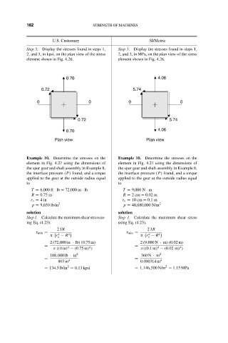
                  Step 5. Display the stresses found in steps 1,  Step 5. Display the stresses found in steps 1,
                  2, and 3, in kpsi, on the plan view of the stress  2, and 3, in MPa, on the plan view of the stress
                  element shown in Fig. 4.26.        element shown in Fig. 4.26.
                                 0.70                               4.06
                        0.72                               5.74

                      0                   0              0                   0


                                      0.72                              5.74

                                 0.70                               4.06
                             Plan view                          Plan view


                  Example 10. Determine the stresses on the  Example 10. Determine the stresses on the
                  element in Fig. 4.27 using the dimensions of  element in Fig. 4.27 using the dimensions of
                  the spur gear and shaft assembly in Example 8,  the spur gear and shaft assembly in Example 8,
                  the interface pressure (P) found, and a torque  the interface pressure (P) found, and a torque
                  applied to the gear at the outside radius equal  applied to the gear at the outside radius equal
                  to                                 to
                    T = 6,000 ft · lb = 72,000 in · lb  T = 9,000 N · m
                    R = 0.75 in                        R = 2cm = 0.02 m
                    r o = 4in                          r o = 10 cm = 0.1 m
                    p = 9,650 lb/in 2                  p = 48,680,000 N/m 2
                  solution                           solution
                  Step 1. Calculate the minimum shear stress us-  Step 1. Calculate the maximum shear stress
                  ing Eq. (4.23).                    using Eq. (4.23).
                              2 TR                              2 TR
                      τ min =                           τ min =
                                                                4
                              4
                           π r − R 4                         π r − R 4
                              o                                 o
                           2 (72,000 in · lb)(0.75 in)       2 (9,000 N · m)(0.02 m)
                         =        4       4                =        4       4
                            π((4in) − (0.75 in) )            π((0.1m) − (0.02 m) )
                           108,000 lb · in 2                  360 N · m 2
                         =                                 =
                              803 in 4                       0.000314 m 4
                                                                       2
                                  2
                         = 134.5 lb/in = 0.13 kpsi         = 1,146,500 N/m = 1.15 MPa
   195   196   197   198   199   200   201   202   203   204   205