
Page 204 - Marks Calculation for Machine Design
P. 204
P1: Shibu
January 4, 2005
14:25
Brown.cls
Brown˙C04
STRENGTH OF MACHINES
186
supports of the tank. For the simply-supported beam with a constant distributed load (w)
in Fig. 4.29, the idealized model for the pressurized tank, the maximum bending moment
(M max ) is given by Eq. (4.35).
1 2
M max = wL (4.35)
8
For other beam configurations and loadings, the maximum bending moment and maxi-
mumshearforce,andtheirlocationsalongthebeam,willbedifferent.Acompletediscussion
of the most common beam configurations and loadings is presented in Chap. 2. Just to be
complete here, the maximum shear force (V max ) occurs at the supports and is given in Eq.
(4.36).
1
V max = wL (4.36)
2
For this beam configuration and loading, the minimum bending moment (M min ), which
is zero, occurs at the supports, and the minimum shear force (V min ), also zero, occurs at the
midpoint between the supports.
The maximum bending stress (σ max ) can be found from Eq. (4.32), where for a thin
circular ring the maximum distance (y max ) from the neutral axis is the mean radius (r m )
and the moment of inertia (I) is given by Eq. (4.34). The expression for maximum bending
stress (σ max ) is developed in Eq. (4.37).
M max y max M max r m M max
σ max = = = (4.37)
2
3
I π r t π r t
m
m
where the maximum bending moment (M max ) is given by Eq. (4.35).
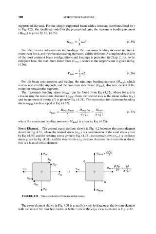
Stress Element. The general stress element shown in Fig. 4.2 becomes the stress element
shown in Fig. 4.31, where the normal stress (σ xx ) is a combination of the axial stress given
by Eq. (4.30) and the bending stress given by Eq. (4.37), the normal stress (σ yy ) is the hoop
stress given by Eq. (4.31), and the shear stress (τ xy ) is zero. Because there is no shear stress,
this is a biaxial stress element.
p r
s yy s hoop = i m
t
t xy
0
t xy p r
s = i m + M
s xx s xx xx 2t 2
→ p r t
m
s xx
t xy
0
t xy
s yy s hoop
FIGURE 4.31 Stress element for bending and pressure.
The stress element shown in Fig. 4.31 is actually a view looking up at the bottom element
with the axis of the tank horizontal. A better view is the edge view as shown in Fig. 4.32.