
Page 207 - Marks Calculation for Machine Design
P. 207
P1: Shibu/Sanjay
14:35
January 4, 2005
Brown.cls
Brown˙C05
CHAPTER 5
PRINCIPAL STRESSES
AND MOHR’S CIRCLE
5.1 INTRODUCTION
In Chap. 4, seven different combinations of loadings were discussed with each resulting in
a particular stress element based on a general plane stress element, like the one shown in
Fig. 4.2 and repeated here in Fig. 5.1.
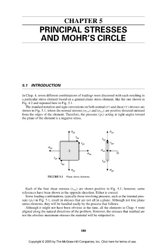
The standard notation and sign conventions on both normal (σ) and shear (τ) stresses are
shown in Fig. 5.1, where the normal stresses (σ xx ) and (σ yy ) are positive directed outward
from the edges of the element. Therefore, the pressure (p i ) acting at right angles toward
the plane of the element is a negative stress.
s yy s yy
t xy t xy
t yx t yx
s xx
s xx
s xx p i
t yx
t xy ¥
t xy
s yy s yy
FIGURE 5.1 Plane stress element.
Each of the four shear stresses (τ xy ) are shown positive in Fig. 5.1; however, some
references have been shown in the opposite direction. Either is correct.
Some loading combinations, typically those involving pressure, such as the internal pres-
sure (p i ) in Fig. 5.1, result in stresses that are not all in a plane. Although not true plane
stress elements, they will be handled easily by the process that follows.
Although it might not have been obvious at the time, all the elements in Chap. 4 were
aligned along the natural directions of the problem. However, the stresses that resulted are
not the absolute maximum stresses the material will be subjected to.
189
Copyright © 2005 by The McGraw-Hill Companies, Inc. Click here for terms of use.