Page 203 - Marks Calculation for Machine Design
P. 203

P1: Shibu
                                      14:25
                          January 4, 2005
                 Brown˙C04
        Brown.cls
                                            COMBINED LOADINGS
                    and a hoop stress (σ hoop ) circumferentially around the tank and given by Eq. (4.31),
                                                  p i r m                         185
                                           σ hoop =   = 2 σ axial               (4.31)
                                                   t
                    which is twice the axial stress, and where (r m ) is the mean radius and (t) is the wall thickness
                    of the tank. The mean radius (r m ) can be taken to be the inside radius of the tank without
                    any loss of accuracy.
                      The tank in Fig. 4.28 can be modeled as the simply-supported beam with a constant
                    distributed load (w) and a length (L) shown in Fig. 4.29. As will be presented in Chap. 2 on
                    beams, this beam configuration and loading produces a bending moment (M) distribution
                    that is maximum at its midpoint and zero at the supports, and a shear force (V ) distribution
                    that is zero at the midpoint but a maximum at the supports.
                                                                          w
                             A                                            B
                                                    L
                             FIGURE 4.29  Simply-supported beam with constant distributed load.
                      The bending moment (M) will produce a bending stress (σ xx ) given by Eq. (4.32),
                                                     My
                                                σ xx =                          (4.32)
                                                      I
                    and the shear force (V ) will produce a shear stress (τ xy ) given by Eq. (4.33),

                                                     VQ
                                                τ xy =                          (4.33)
                                                      Ib
                    where (b) is the thickness (t) and the moment of inertia (I) is given by Eq. (4.34).
                                                      3
                                                 I = πr t                       (4.34)
                                                      m
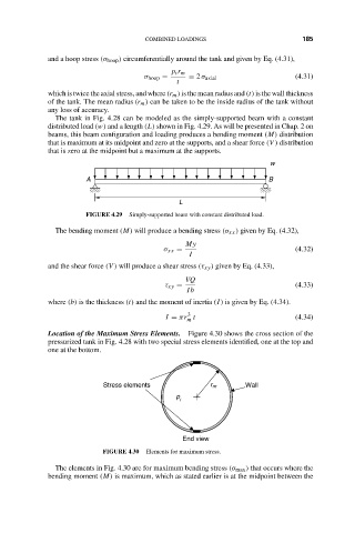
                    Location of the Maximum Stress Elements.  Figure 4.30 shows the cross section of the
                    pressurized tank in Fig. 4.28 with two special stress elements identified, one at the top and
                    one at the bottom.


                                 Stress elements           r m      Wall
                                                   p
                                                    i


                                                     End view
                                 FIGURE 4.30  Elements for maximum stress.
                      The elements in Fig. 4.30 are for maximum bending stress (σ max ) that occurs where the
                    bending moment (M) is maximum, which as stated earlier is at the midpoint between the
   198   199   200   201   202   203   204   205   206   207   208