
Page 206 - Marks Calculation for Machine Design
P. 206
P1: Shibu
January 4, 2005
Brown˙C04
Brown.cls
188
U.S. Customary 14:25 STRENGTH OF MACHINES SI/Metric
Step 4. Using the maximum bending moment Step 4. Using the maximum bending moment
(M max ) found in step 3 calculate the maximum (M max ) found in step 3 calculate the maximum
bending stress (σ max ) from Eq. (4.37). bending stress (σ max ) from Eq. (4.37).
M max M max
σ max = σ max =
2
2
π r t π r t
m
m
(129,000 lb · ft)(12 in/ft) (194,000 N · m)
= =
2
2
π(36 in) (0.5in) π(1m) (0.013 m)
1,548,000 lb · in 194,000 N · m
= =
2036 in 3 0.0408 m 3
2
2
= 760 lb/in = 0.8 kpsi = 4,750,000 N/m = 4.8MPa
Step 5. Combine the axial stress (σ axial ) found Step 5. Combine the axial stress (σ axial ) found
in step 1 with the maximum bending stress in step 1 with the maximum bending stress
(σ max ) found in step 4 to give a maximum nor- (σ max ) found in step 4 to give a maximum nor-
mal stress (σ xx ). mal stress (σ xx )
σ xx = σ axial + σ max σ xx = σ axial + σ max
= (7.2 kpsi) + (0.8 kpsi) = (53.8 kpsi) + (4.8 kpsi)
= 8.0 kpsi = 58.6 kpsi
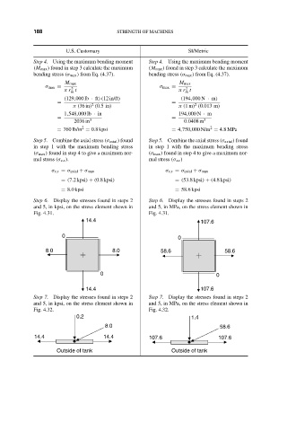
Step 6. Display the stresses found in steps 2 Step 6. Display the stresses found in steps 2
and 5, in kpsi, on the stress element shown in and 5, in MPa, on the stress element shown in
Fig. 4.31. Fig. 4.31.
14.4 107.6
0 0
8.0 8.0 58.6 58.6
0 0
14.4 107.6
Step 7. Display the stresses found in steps 2 Step 7. Display the stresses found in steps 2
and 5, in kpsi, on the stress element shown in and 5, in MPa, on the stress element shown in
Fig. 4.32. Fig. 4.32.
0.2 1.4
8.0 58.6
14.4 14.4 107.6 107.6
Outside of tank Outside of tank