
Page 208 - Marks Calculation for Machine Design
P. 208
P1: Shibu/Sanjay
January 4, 2005
14:35
Brown.cls
Brown˙C05
STRENGTH OF MACHINES
190
PRINCIPAL STRESSES
5.2
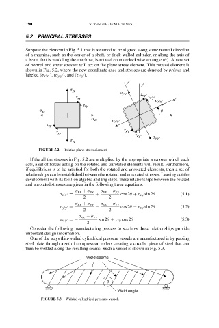
Suppose the element in Fig. 5.1 that is assumed to be aligned along some natural direction
of a machine, such as the center of a shaft, or thick-walled cylinder, or along the axis of
a beam that is modeling the machine, is rotated counterclockwise an angle (θ). A new set
of normal and shear stresses will act on the plane stress element. This rotated element is
shown in Fig. 5.2, where the new coordinate axes and stresses are denoted by primes and
labeled (σ x x ),(σ y y ), and (τ x y ).
y¢
y
s yy s
t xy y¢y¢ t x¢y¢ t x¢y¢
s x¢x¢ x¢
t xy
s xx q
x
s xx s
t xy x¢x¢
t
t xy x¢y¢
t x¢y¢
s y¢y¢
s yy
FIGURE 5.2 Rotated plane stress element.
If the all the stresses in Fig. 5.2 are multiplied by the appropriate area over which each
acts, a set of forces acting on the rotated and unrotated elements will result. Furthermore,
if equilibrium is to be satisfied for both the rotated and unrotated elements, then a set of
relationships can be established between the rotated and unrotated stresses. Leaving out the
development with its bzillion algebra and trig steps, these relationships between the rotated
and unrotated stresses are given in the following three equations:
σ xx + σ yy σ xx − σ yy
σ x x = + cos 2θ + τ xy sin 2θ (5.1)
2 2
σ xx + σ yy σ xx − σ yy
σ y y = − cos 2θ − τ xy sin 2θ (5.2)
2 2
σ xx − σ yy
τ x y =− sin 2θ + τ xy cos 2θ (5.3)
2
Consider the following manufacturing process to see how these relationships provide
important design information.
One of the ways thin-walled cylindrical pressure vessels are manufactured is by passing
steel plate through a set of compression rollers creating a circular piece of steel that can
then be welded along the resulting seams. Such a vessel is shown in Fig. 5.3.
Weld seams
q
Weld angle
FIGURE 5.3 Welded cylindrical pressure vessel.