Page 205 - Marks Calculation for Machine Design
P. 205

P1: Shibu
                          January 4, 2005
                                      14:25
        Brown.cls
                 Brown˙C04
                                            COMBINED LOADINGS
                                             p
                                              i
                                                                i  m
                                                           s xx  =  p r  +  M     187
                                                                2t  p r  t
                                                                      2
                                                                       m
                                                           p r
                                s hoop  Outside of tank  s hoop  =   i  m
                                                            t
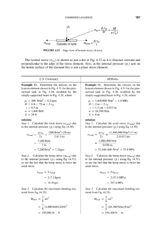
                                FIGURE 4.32  Edge view of bottom stress element.
                      The normal stress (σ xx ) is shown as just a dot in Fig. 4.32 as it is directed outward and
                    perpendicular to the edge of the stress element. Also, as the internal pressure (p i ) acts on
                    the inside surface of the element this is not a plane stress element.
                              U.S. Customary                      SI/Metric
                    Example 11. Determine the stresses on the  Example 11. Determine the stresses on the
                    bottom element shown in Fig. 4.31 for the pres-  bottom element shown in Fig. 4.31 for the pres-
                    surized tank in Fig. 4.28, modeled by the  surized tank in Fig. 4.28, modeled by the
                    simply-supported beam in Fig. 4.29, where  simply-supported beam in Fig. 4.29, where
                                                                      2
                               2
                      p i = 200 lb/in = 0.2 kpsi        p i = 1,400,000 N/m = 1.4MPa
                      D = 6ft = 72 in = 2 r m           D = 2m = 2 r m
                      t = 0.5 in                         t = 1.3 cm = 0.013 m
                      w = 1,800 lb/ft                   w = 24,300 N/m
                      L = 24 ft                          L = 8m
                    solution                           solution
                    Step 1. Calculate the axial stress (σ axial ) due  Step 1. Calculate the axial stress (σ axial ) due
                    to the internal pressure (p i ) using Eq. (4.30).  to the internal pressure (p i ) using Eq. (4.30).
                                                                              2
                                         2
                             p i r m  (200 lb/in )(36 in)     p i r m  (1,400,000 N/m )(1m)
                       σ axial =  =                     σ axial =  =
                              2 t     2 (0.5in)                2 t      2 (0.013 m)
                             7,200 lb/in                      1,400,000 N/m
                           =                                =
                               1in                              0.026 m
                                                                        2
                                   2
                           = 7,200 lb/in = 7.2 kpsi         = 53,846,000 N/m = 53.8MPa
                    Step 2.  Calculate the hoop stress (σ hoop ) due  Step 2.  Calculate the hoop stress (σ hoop ) due
                    to the internal pressure (p i ) using Eq. (4.31),  to the internal pressure (p i ) using Eq. (4.31),
                    or use the fact that the hoop stress is twice the  or use the fact that the hoop stress is twice the
                    axial stress                       axial stress.
                            σ hoop = 2 σ axial                σ hoop = 2 σ axial
                                = 2 (7.2 kpsi)                    = 2 (53.8MPa)
                                = 14.4 kpsi                       = 107.6MPa
                    Step 3. Calculate the maximum bending mo-  Step 3. Calculate the maximum bending mo-
                    ment from Eq. (4.35).              ment from Eq. (4.35).
                               1  2                               1  2
                         M max =  wL                       M max =  wL
                               8                                  8
                               1                                  1
                             =  (1,800 lb/ft)(24 ft) 2         =   (24,300 N/m)(8m) 2
                               8                                  8
                             = 129,000 lb · ft                 = 194,400 N · m
   200   201   202   203   204   205   206   207   208   209   210