
Page 202 - Marks Calculation for Machine Design
P. 202
P1: Shibu
January 4, 2005
Brown˙C04
Brown.cls
184
U.S. Customary 14:25 STRENGTH OF MACHINES SI/Metric
Step 5. Display the stresses found in steps 1, Step 5. Display the stresses found in steps 1,
2, and 3, in kpsi, on the plan view of the stress 2, and 3, in MPa, on the plan view of the stress
element shown in Fig. 4.27. element shown in Fig. 4.27.
10.35 52.74
0.13 1.15
0 0 0 0
0.13 1.15
10.35 52.74
Plan view Plan view
From the magnitudes of the stresses calculated in Examples 9 and 10, the stress element
at the interface radius (R) has the maximum stresses. Note that the stress element at the
interface radius is not a plane stress element due to the presence of the radial stress acting
perpendicular to the top and the bottom surfaces. More will be said about this kind of stress
element in the next chapter.
Also notice that even though a negative value was obtained for the radial stress, the
negative sign is accounted for in the direction shown on the stress element.
Consider one last combination of loadings from Tables 4.1 and 4.2, bending and pressure.
4.8 BENDING AND PRESSURE
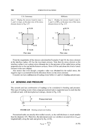
The seventh and last combination of loadings to be considered is bending and pressure.
This type of loading occurs when a large pressurized tank is supported near its ends like the
cylindrical tank, with hemispherical endcaps, shown in Fig. 4.28.
D Pressurized tank
L
FIGURE 4.28 Bending and pressure loading.
Pressurized tanks are usually thin-walled vessels, as the wall thickness is much smaller
than the diameter (D). Therefore, the internal pressure (p i ) produces an axial stress (σ axial )
longitudinally along the tank and given by Eq. (4.30),
p i r m
σ axial = (4.30)
2 t