Page 197 - Marks Calculation for Machine Design
P. 197

P1: Shibu
                          January 4, 2005
                                      14:25
        Brown.cls
                 Brown˙C04
                                            COMBINED LOADINGS
                                                                                  179
                    and the radial stress (σ r ) given in Eq. (4.25) becomes a minimum value (σ
                                                                        r min ), and as stated
                    earlier is equal to zero, with the algebraic steps shown in Eq. (4.29).
                                       pR 2  
        2 
   pR 2
                                min               r o
                               σ r  =        1 −        =        [1 − 1] = 0    (4.29)
                                                           2
                                      2
                                     r − R 2              r − R 2
                                      o           r o      o


                                                          simplify bracket terms
                                        Eq. (1.91) with r=r o
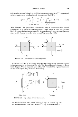
                    Stress Elements. The general stress element shown in Fig. 4.2 becomes the stress element
                    shown in Fig. 4.24, where the normal stress (σ xx ) is the tangential stress (σ t ) given by
                    Eq. (4.24) due to the interface pressure (P), the normal stress (σ yy ) is zero, and the shear
                    stress (τ xy ) is the shear stress due to the torque (T ) given by Eq. (4.20).
                                     s yy                         0
                                       t xy                t xy
                                          t xy           t xy
                         s xx                          s xx               s  = s t
                                                                           xx
                                                  →
                                             s xx
                            t xy                                       t xy  =   Tr
                                t xy                                 t xy   J
                                     s yy                         0
                         FIGURE 4.24  Stress element for torsion and pressure.
                      The stress element in Fig. 4.25 is somewhat misleading in that it is not oriented according
                    to the arrangement of the elements in Fig. 4.23. Also, the radial stress (σ r ) cannot be shown
                    in this diagram. A better diagram is given in Fig. 4.26, where both the edge and plan views
                    are provided, aligned along the axis of the assembly.
                                        2      2 
                                      pR      r   o 
                                  s t =    1 +                 s t
                                         2
                                      2
                                     r − R      r   
                                      o
                                                            t xy
                                                          t xy
                                           2      2 
                                        pR       r   o 
                          s r       s r =     1 −        0              0  Axis
                                       r − R      r   
                                        2
                                           2
                                        o
                                      Tr                                    Tr
                                  t xy  =                               t xy  =
                                      J                                      J
                                                                      t xy
                                  s t                              s t
                             Edge view                        Plan view
                        FIGURE 4.25  Edge and plan views of stress element.
                      For the stress element at the outside radius (r o ), Fig. 4.25 becomes Fig. 4.26.
                      For the stress element at the radial interface (R), Fig. 4.25 becomes Fig. 4.27.
   192   193   194   195   196   197   198   199   200   201   202