
Page 209 - Marks Calculation for Machine Design
P. 209
P1: Shibu/Sanjay
14:35
January 4, 2005
Brown˙C05
Brown.cls
191
PRINCIPAL STRESSES AND MOHR’S CIRCLE
The angle (θ) in Fig. 5.3 is the weld angle and it is the stresses relative to this angle
that are most important to the design engineer. However, it is the stresses relative to the
natural axis of the cylinder that are found first, using the equations presented in Sec. 3.1.1.
Then Eqs. (5.1) to (5.3) are used to find the stresses along the direction defined by the
angle (θ).
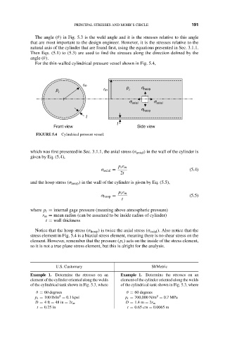
For the thin-walled cylindrical pressure vessel shown in Fig. 5.4,
rm
p s
p rm i hoop
i
s axial s axial
s hoop
t
t
Front view Side view
FIGURE 5.4 Cylindrical pressure vessel.
which was first presented in Sec. 3.1.1, the axial stress (σ axial ) in the wall of the cylinder is
given by Eq. (5.4),
p i r m
σ axial = (5.4)
2t
and the hoop stress (σ hoop ) in the wall of the cylinder is given by Eq. (5.5),
p i r m
σ hoop = (5.5)
t
where p i = internal gage pressure (meaning above atmospheric pressure)
r m = mean radius (can be assumed to be inside radius of cylinder)
t = wall thickness
Notice that the hoop stress (σ hoop ) is twice the axial stress (σ axial ). Also notice that the
stress element in Fig. 5.4 is a biaxial stress element, meaning there is no shear stress on the
element. However, remember that the pressure (p i ) acts on the inside of the stress element,
so it is not a true plane stress element, but this is alright for the analysis.
U.S. Customary SI/Metric
Example 1. Determine the stresses on an Example 1. Determine the stresses on an
element of the cylinder oriented along the welds element of the cylinder oriented along the welds
of the cylindrical tank shown in Fig. 5.3, where of the cylindrical tank shown in Fig. 5.3, where
θ = 60 degrees θ = 60 degrees
2
2
p i = 100 lb/in = 0.1 kpsi p i = 700,000 N/m = 0.7 MPa
D = 4ft = 48 in = 2r m D = 1.4 m = 2r m
t = 0.25 in t = 0.65 cm = 0.0065 m