
Page 215 - Marks Calculation for Machine Design
P. 215
P1: Shibu/Sanjay
14:35
January 4, 2005
Brown˙C05
Brown.cls
PRINCIPAL STRESSES AND MOHR’S CIRCLE
U.S. Customary SI/Metric 197
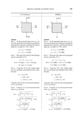
9.6 75.4
0 0
4.8 4.8 37.7 37.7
0 0
9.6
solution solution
Step 1. As the unrotated shear stress (τ xy ) is Step 1. As the unrotated shear stress (τ xy ) is
zero, the unrotated stress element is actually the zero, the unrotated stress element is actually the
principal stress element, except that the rotation principal stress element, except that the rotation
angle (φ p ) is equal to (± 90 ), and so angle (φ p ) is equal to (± 90 ), and so
◦
◦
σ 1 = σ yy = 9.6 kpsi σ 1 = σ yy = 75.4MPa
σ 2 = σ xx = 4.8 kpsi σ 2 = σ xx = 37.7MPa
Step 2. Obviously, the values for the principal Step 2. Obviously, the values for the principal
stresses satisfy Eq. (5.17). stresses satisfy Eq. (5.17).
σ 1 + σ 2 = σ xx + σ yy σ 1 + σ 2 = σ xx + σ yy
(9.4 + 4.8 ) kpsi = (4.8 + 9.6) kpsi (75.4 + 37.7) MPa = (37.7 + 75.4) MPa
14.4 kpsi ≡ 14.4 kpsi 113.1MPa ≡ 113.1MPa
Step 3. Using Eq. (5.11), the rotation angle Step 3. Using Eq. (5.11), the rotation angle
(φ s ) for maximum and minimum shear stress (φ s ) for maximum and minimum shear stress
becomes becomes
φ s = φ p ± 45 ◦ φ s = φ p ± 45 ◦
◦
◦
=±90 ± 45 ◦ =±90 ± 45 ◦
=±135 or ± 45 ◦ =±135 or ± 45 ◦
◦
◦
where the values in the first and fourth quadrants where the values in the first and fourth quadrants
(±45 ) are chosen. (±45 ) are chosen.
◦
◦
Step 4. Using Eq. (5.12), the maximum shear Step 4. Using Eq. (5.12), the maximum shear
stress (τ max ) becomes stress (τ max ) becomes
2 2
σ xx − σ yy 2 σ xx − σ yy 2
τ max = + τ xy τ max = + τ xy
2 2
2 2
4.8 − 9.6) kpsi 37.7 − 75.4) MPa
= + (0) 2 = + (0) 2
2 2
2 2
−4.8 kpsi −37.7MPa
= =
2 2
2
2
= (−2.4 kpsi) = 2.4 kpsi = (−18.85 MPa) = 18.85 MPa