Page 219 - Marks Calculation for Machine Design
P. 219

P1: Shibu/Sanjay
                                      14:35
                          January 4, 2005
        Brown.cls
                 Brown˙C05
                                     PRINCIPAL STRESSES AND MOHR’S CIRCLE
                              U.S. Customary                      SI/Metric       201
                          = (7.65 + 6.85 + 1.69) kpsi      = (73.35 + 65.58 + 16.44) MPa
                          = 16.19 kpsi = σ 1               = 155.37 MPa
                     So the rotation angle found in step 5 is for the  So the rotation angle found in step 5 is for the
                    maximum principal stress (σ 1 ).   maximum principal stress (σ 1 ).
                    Step 7. Using Eq. (5.11), the rotation angle  Step 7. Using Eq. (5.11), the rotation angle
                    (φ s ) for the maximum shear stress becomes  (φ s ) for the maximum shear stress becomes
                                  ◦
                                        ◦
                                                                    ◦
                                                                           ◦
                        φ s = φ p ± 45 =−13.2 ± 45 ◦       φ s = φ p ± 45 =−13.3 ± 45 ◦
                          = 31.8 ◦  or −58.2 ◦               = 31.7 ◦  or −58.3 ◦
                    where for reasons that will be presented in the  where for reasons that will be presented in the
                    discussion on Mohr’s circle, the negative value  discussion on Mohr’s circle, the negative value
                    (−58.2 ) will be chosen.           (−58.3 ) will be chosen.
                                                           ◦
                        ◦
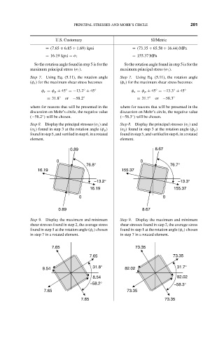
                    Step 8. Display the principal stresses (σ 1 ) and  Step 8. Display the principal stresses (σ 1 ) and
                    (σ 2 ) found in step 3 at the rotation angle (φ p )  (σ 2 ) found in step 3 at the rotation angle (φ p )
                    found in step 5,and verified in step 6, in a rotated  found in step 5, and verified in step 6, in a rotated
                    element.                           element.
                                   0.89                             8.67
                              0                               0
                                          76.8°                           76.7°
                       16.19                           155.37
                                             –13.2°                          –13.3°
                                           16.19                           155.37

                                       0                               0
                               0.89                            8.67

                    Step 9. Display the maximum and minimum  Step 9. Display the maximum and minimum
                    shear stresses found in step 2, the average stress  shear stresses found in step 2, the average stress
                    found in step 1 at the rotation angle (φ s ) chosen  found in step 1 at the rotation angle (φ s ) chosen
                    in step 7 in a rotated element.    in step 7 in a rotated element.


                            7.65                            73.35
                                           7.65                            73.35
                                            31.8°                           31.7°
                         8.54                           82.02
                                            8.54                             82.02
                                           –58.2°                          –58.3°
                         7.65                            73.35
                                       7.65                             73.35
   214   215   216   217   218   219   220   221   222   223   224