
Page 223 - Marks Calculation for Machine Design
P. 223
P1: Shibu/Sanjay
January 4, 2005
14:35
Brown.cls
Brown˙C05
PRINCIPAL STRESSES AND MOHR’S CIRCLE
U.S. Customary SI/Metric 205
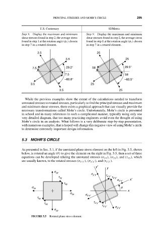
Step 9. Display the maximum and minimum Step 9. Display the maximum and minimum
shear stresses found in step 2, the average stress shear stresses found in step 2, the average stress
found in step 1 at the rotation angle (φ s ) chosen found in step 1 at the rotation angle (φ s ) chosen
in step 7 in a rotated element. in step 7 in a rotated element.
3.5 25
3.5 25
29.2° 29.5°
7.5 58
7.5 58
–60.8° –60.5°
3.5 25
3.5 25
While the previous examples show the extent of the calculations needed to transform
unrotated stresses to rotated stresses, particularly to find the principal stresses and maximum
and minimum shear stresses, there exists a graphical approach that can visually provide the
necessary transformations called Mohr’s circle. Unfortunately, Mohr’s circle is presented
in school and in many references in such a complicated manner, typically using only one
very detailed diagram, that too many practicing engineers avoid even the thought of using
Mohr’s circle in an analysis. What follows is a very deliberate step-by-step presentation,
with numerous examples, that is hoped will change this negative view of using Mohr’s circle
to determine extremely important design information.
5.3 MOHR’S CIRCLE
As presented in Sec. 5.1, if the unrotated plane stress element on the left in Fig. 5.5, shown
below, is rotated an angle (θ) to give the element on the right in Fig. 5.5, then a set of three
equations can be developed relating the unrotated stresses (σ xx ),(σ yy ), and (τ xy ), which
are usually known, to the rotated stresses (σ x x ),(σ y y ), and (τ x y ).
y′
y
s yy
s y′y′ t
t xy x′y′ t x′y′
s x′x′ x′
t xy
s xx q
x
s xx s
t xy x′x′
t xy t x′y′
t x′y′
s y′y′
s yy
FIGURE 5.5 Rotated plane stress element.