
Page 228 - Marks Calculation for Machine Design
P. 228
P1: Shibu/Sanjay
January 4, 2005
Brown˙C05
Brown.cls
210
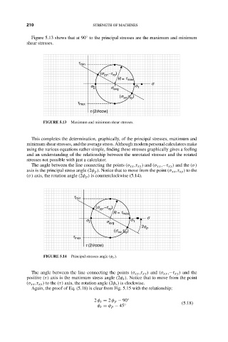
Figure 5.13 shows that at 90 to the principal stresses are the maximum and minimum
shear stresses. 14:35 ◦ STRENGTH OF MACHINES
t min
(s ,-t )
yy
xy
R = t max
s
s 2 s 1
s avg
,t )
(s xx xy
t max
t (2q ccw)
FIGURE 5.13 Maximum and minimum shear stresses.
This completes the determination, graphically, of the principal stresses, maximum and
minimum shear stresses, and the average stress. Although modern personal calculators make
using the various equations rather simple, finding these stresses graphically gives a feeling
and an understanding of the relationship between the unrotated stresses and the rotated
stresses not possible with just a calculator.
The angle between the line connecting the points (σ xx ,τ xy ) and (σ xx ,−τ xy ) and the (σ)
axis is the principal stress angle (2φ p ). Notice that to move from the point (σ xx ,τ xy ) to the
(σ) axis, the rotation angle (2φ p ) is counterclockwise (5.14).
t min
(s ,-t )
yy
xy
R = t max
s
s 2 s avg s 1
2f p
(s ,t )
xx xy
t max
t (2q ccw)
FIGURE 5.14 Principal stresses angle (φ p ).
The angle between the line connecting the points (σ xx ,τ xy ) and (σ xx ,−τ xy ) and the
positive (τ) axis is the maximum stress angle (2φ s ). Notice that to move from the point
(σ xx ,τ xy ) to the (τ) axis, the rotation angle (2φ s ) is clockwise.
Again, the proof of Eq. (5.18) is clear from Fig. 5.15 with the relationship:
2 φ s = 2 φ p − 90 ◦ (5.18)
φ s = φ p − 45 ◦