
Page 232 - Marks Calculation for Machine Design
P. 232
P1: Shibu/Sanjay
January 4, 2005
14:35
Brown˙C05
Brown.cls
STRENGTH OF MACHINES
214
Enlarging the section containing the principal stress angle (2φ p ) gives:
(10,–4)
4
2 f p
11
3.5 6.5
Applyingthedefinitionofthetangentfunctiontotherighttrianglecontainingtheprincipal
stress angle (2φ p ), and using the dimensions shown, gives
opposite 4 kpsi
tan 2φ p = = = 0.615
adjacent 6.5 kpsi
However, as the rotation is clockwise the principal stress angle (φ p ) will be negative.
Changing the sign on (tan 2φ p ) and solving for the angle (φ p ) gives the same value as was
found in Example 5 in Sec. 5.1, that is (−15.8 ).
◦
tan 2φ p =−0.615
2φ p =−31.6 ◦
φ p =−15.8 ◦
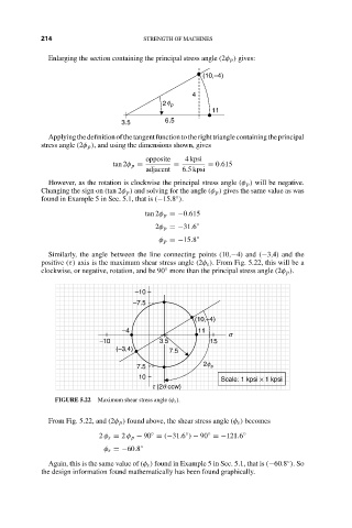
Similarly, the angle between the line connecting points (10,−4) and (−3,4) and the
positive (τ) axis is the maximum shear stress angle (2φ s ). From Fig. 5.22, this will be a
clockwise, or negative, rotation, and be 90 more than the principal stress angle (2φ p ).
◦
–10
–7.5
(10,–4)
–4 11
s
–10 3.5 15
(–3,4) 7.5
7.5 2f s
10 Scale: 1 kpsi × 1 kpsi
t (2q ccw)
FIGURE 5.22 Maximum shear stress angle (φ s ).
From Fig. 5.22, and (2φ p ) found above, the shear stress angle (φ s ) becomes
◦
◦
◦
2 φ s = 2 φ p − 90 = (−31.6 ) − 90 =−121.6 ◦
φ s =−60.8 ◦
◦
Again, this is the same value of (φ s ) found in Example 5 in Sec. 5.1, that is (−60.8 ).So
the design information found mathematically has been found graphically.