Page 231 - Marks Calculation for Machine Design
P. 231

P1: Shibu/Sanjay
                                      14:35
                          January 4, 2005
                 Brown˙C05
        Brown.cls
                                     PRINCIPAL STRESSES AND MOHR’S CIRCLE
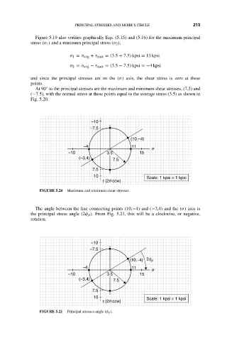
                      Figure 5.19 also verifies graphically Eqs. (5.15) and (5.16) for the maximum principal
                    stress (σ 1 ) and a minimum principal stress (σ 2 ),          213
                                   σ 1 = σ avg + τ max = (3.5 + 7.5) kpsi = 11 kpsi
                                   σ 2 = σ avg − τ max = (3.5 − 7.5) kpsi =−4 kpsi
                    and since the principal stresses are on the (σ) axis, the shear stress is zero at these
                    points.
                          ◦
                      At 90 to the principal stresses are the maximum and minimum shear stresses, (7.5) and
                    (−7.5), with the normal stress at these points equal to the average stress (3.5) as shown in
                    Fig. 5.20.

                                           –10
                                           –7.5
                                                          (10,–4)
                                        –4                11
                                                                  s
                                  –10            3.5         15
                                      (–3,4)       7.5
                                           7.5
                                            10                  Scale: 1 kpsi × 1 kpsi
                                               t (2q ccw)

                       FIGURE 5.20  Maximum and minimum shear stresses.


                      The angle between the line connecting points (10,−4) and (−3,4) and the (σ) axis is
                    the principal stress angle (2φ p ). From Fig. 5.21, this will be a clockwise, or negative,
                    rotation.


                                           –10
                                          –7.5

                                                          (10,–4)  2f p
                                        –4                11
                                                                  s
                                  –10            3.5         15
                                      (–3,4)       7.5
                                           7.5
                                            10                  Scale: 1 kpsi × 1 kpsi
                                               t (2q ccw)
                       FIGURE 5.21  Principal stresses angle (φ p ).
   226   227   228   229   230   231   232   233   234   235   236