
Page 227 - Marks Calculation for Machine Design
P. 227
P1: Shibu/Sanjay
January 4, 2005
14:35
Brown.cls
Brown˙C05
PRINCIPAL STRESSES AND MOHR’S CIRCLE
(s , –t ) 209
xy
yy
s
s avg
(s , t )
xy
xx
t (2q ccw)
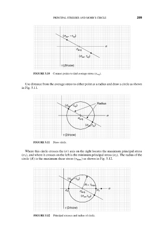
FIGURE 5.10 Connect points to find average stress (σ avg ).
Use distance from the average stress to either point as a radius and draw a circle as shown
in Fig. 5.11.
Radius
, –t )
(s yy xy
s
s avg
, t )
(s xx xy
t (2q ccw)
FIGURE 5.11 Draw circle.
Where this circle crosses the (σ) axis on the right locates the maximum principal stress
(σ 1 ), and where it crosses on the left is the minimum principal stress (σ 2 ). The radius of the
circle (R) is the maximum shear stress (τ max ) as shown in Fig. 5.12.
(s , -t )
xy
yy
R = t max
s
s
s avg
s 2 1
,t )
(s xx xy
t (2q ccw)
FIGURE 5.12 Principal stresses and radius of circle.