
Page 225 - Marks Calculation for Machine Design
P. 225
P1: Shibu/Sanjay
January 4, 2005
14:35
Brown.cls
Brown˙C05
207
PRINCIPAL STRESSES AND MOHR’S CIRCLE
Mohr’s Circle.
The proof of Eq. (5.18), and other relationships and design information,
can be discovered using Mohr’s circle. The origin and development of Mohr’s circle is very
interesting and is contained in any number of excellent references. For the purposes of this
book focusing on calculations, the origin and development will be omitted.
One important usefulness of Mohr’s circle is to display the maximum and minimum
principal stresses, the maximum and minimum shear stresses, and the average stress once
they are determined. Such a Mohr’s circle is shown in Fig. 5.6.
t min
R = t max 2q
s
s 2 s s 1
avg
–2q
t max
t (2q ccw)
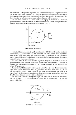
FIGURE 5.6 Mohr’s circle.
Notice that the average stress (σ avg ) locates the center of Mohr’s circle and the maximum
shear stress (τ max ) is the radius (R). The horizontal axis is the normal stress (σ) and the
vertical axis is the shear stress (τ), where positive (τ) is downward so that the rotation
angle (2θ) on Mohr’s circle is in the same counterclockwise (ccw) direction as the rotation
angle (θ) on the plane stress element.
The proof of Eq. (5.18) is now clear that to go from the point on the circle of maximum
principal stress (σ 1 ) to the point on the circle for maximum shear stress (τ max ) the angle of
rotation (2θ) is clockwise, or a minus 90 , so the angle (θ) would be half this value, or a
◦
minus 45 clockwise.
◦
Also notice that Mohr’s circle verifies Eqs. (5.15) and (5.16), where the maximum prin-
cipal stress (σ 1 ) is the average stress (σ avg ) plus the maximum shear stress (τ max ), and
the minimum principal stress (σ 2 ) is the average stress (σ avg ) minus the maximum shear
stress (τ max ). As the maximum and minimum shear stresses (τ max ) and (τ min ) are opposites,
Fig. 5.6 shows them at opposite points on the circle.
The circle does not always end up on the right side of the vertical (τ) axis. It can straddle
the axis as in Fig. 5.7, or be completely on the left side of the vertical (τ) axis like that
shown in Fig. 5.8.
t min
R = t max 2q
s
s 2 s s 1
avg
–2q
t max
t (2q ccw)
FIGURE 5.7 Mohr’s circle.