
Page 235 - Marks Calculation for Machine Design
P. 235
P1: Shibu/Sanjay
January 4, 2005
14:35
Brown˙C05
Brown.cls
PRINCIPAL STRESSES AND MOHR’S CIRCLE
–75 217
–56.5
(75,–30)
–30.5 82.5
s
–75 26 120
(–25,30) 56.5
56.5
75 Scale: 7.5 MPa ¥ 7.5 MPa
t (2q ccw)
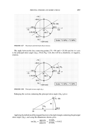
FIGURE 5.27 Maximum and minimum shear stresses.
The angle between the line connecting points (75,−30) and (−25,30) and the (σ) axis
is the principal stress angle (2φ p ). From Fig. 5.28, this will be a clockwise, or negative,
rotation.
–75
–56.5
(75,–30) 2f p
–30.5 82.5
s
–75 26 120
(–25,30) 56.5
56.5
75 Scale: 7.5 MPa ¥ 7.5 MPa
t (2q ccw)
FIGURE 5.28 Principal stresses angle (φ p ).
Enlarging the section containing the principal stress angle (2φ p ) gives:
(75,–30)
30
2f p
82.5
26 49
Applyingthedefinitionofthetangentfunctiontotherighttrianglecontainingtheprincipal
stress angle (2φ p ), and using the dimensions shown, gives
opposite 30 MPa
tan 2φ p = = = 0.612
adjacent 49 MPa