
Page 239 - Marks Calculation for Machine Design
P. 239
P1: Shibu/Sanjay
January 4, 2005
14:35
Brown.cls
Brown˙C05
PRINCIPAL STRESSES AND MOHR’S CIRCLE
221
Where the circle crosses the (σ) axis on the right, locates the maximum principal stress
(σ 1 ), and where it crosses on the left, is the minimum principal stress (σ 2 ). For the uniaxial
element,themaximumprincipalstress(σ 1 )isthegivenstress(σ)andtheminimumprincipal
stress (σ 2 ) is zero. This means the uniaxial element is actually the principal stress element.
Also, the radius of the circle (R) in Fig. 5.36 is the maximum shear stress (τ max ), which
here is the same as the average stress (σ/2).
(0,0) (s/2) (s,0)
s
s 2 s 1
(s/2)
t (2q ccw)
FIGURE 5.36 Principal stresses and radius of circle.
◦
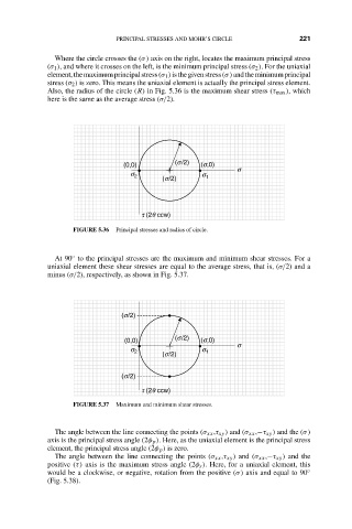
At 90 to the principal stresses are the maximum and minimum shear stresses. For a
uniaxial element these shear stresses are equal to the average stress, that is, (σ/2) and a
minus (σ/2), respectively, as shown in Fig. 5.37.
(s/2)
(0,0) (s/2) (s,0)
s
s 2 s 1
(s/2)
(s/2)
t (2q ccw)
FIGURE 5.37 Maximum and minimum shear stresses.
The angle between the line connecting the points (σ xx ,τ xy ) and (σ xx ,−τ xy ) and the (σ)
axis is the principal stress angle (2φ p ). Here, as the uniaxial element is the principal stress
element, the principal stress angle (2φ p ) is zero.
The angle between the line connecting the points (σ xx ,τ xy ) and (σ xx ,−τ xy ) and the
positive (τ) axis is the maximum stress angle (2φ s ). Here, for a uniaxial element, this
would be a clockwise, or negative, rotation from the positive (σ) axis and equal to 90 ◦
(Fig. 5.38).