Page 243 - Marks Calculation for Machine Design
P. 243

P1: Shibu/Sanjay
                                      14:35
                          January 4, 2005
        Brown.cls
                 Brown˙C05
                                     PRINCIPAL STRESSES AND MOHR’S CIRCLE
                                                                                  225
                      At 90 to the principal stresses are the maximum and minimum shear stresses. For a
                          ◦
                    biaxial element these shear stresses are equal to (σ/2) and a minus (σ/2), respectively, as
                    shown in Fig. 5.43.
                             (s/2)
                                                      (s/2)
                                             (s,0)              (2s,0)
                                                                     s
                                               s 2              s 1
                                                      (3s/2)
                             (s/2)
                                  t (2q ccw)
                          FIGURE 5.43  Maximum and minimum shear stresses.

                      The angle between the line connecting the points (σ xx ,τ xy ) and (σ xx ,−τ xy ) and the (σ)
                    axis is the principal stress angle (2φ p ). Here, as the biaxial element is the principal stress
                    element, the principal stress angle (2φ p ) is zero.
                      The angle between the line connecting the points (σ xx ,τ xy ) and (σ xx ,−τ xy ) and the
                    positive (τ) axis is the maximum stress angle (2φ s ). Here, as in Fig. 5.44 for a biaxial
                    element, this would be a clockwise, or negative, rotation from the positive (σ) axis and
                    equal to 90 .
                            ◦


                             (s/2)
                                                      (s/2)
                                             (s,0)              (2s,0)
                                                                     s
                                               s 2    (3s/2)    s 1

                             (s/2)                               2f = –90∞
                                                                  s
                                  t (2q ccw)

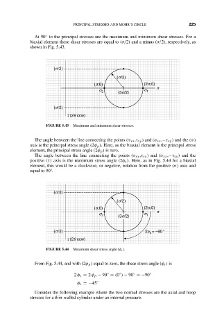
                          FIGURE 5.44  Maximum shear stress angle (φ s ).

                      From Fig. 5.44, and with (2φ p ) equal to zero, the shear stress angle (φ s ) is

                                                            ◦
                                                  ◦
                                                       ◦
                                     2 φ s = 2 φ p − 90 = (0 ) − 90 =−90 ◦
                                      φ s =−45 ◦
                      Consider the following example where the two normal stresses are the axial and hoop
                    stresses for a thin-walled cylinder under an internal pressure.
   238   239   240   241   242   243   244   245   246   247   248