
Page 241 - Marks Calculation for Machine Design
P. 241
P1: Shibu/Sanjay
14:35
January 4, 2005
Brown˙C05
Brown.cls
PRINCIPAL STRESSES AND MOHR’S CIRCLE
U.S. Customary SI/Metric 223
Step3. FromFig.5.37,themaximumandmin- Step3. FromFig.5.37,themaximumandmin-
imum shear stresses are shown 90 to the prin- imum shear stresses are shown 90 to the prin-
◦
◦
cipal stresses, and equal to the average stress. cipal stresses, and equal to the average stress.
σ 12 kpsi σ 84 MPa
τ max = σ avg = = = 6 kpsi τ max = σ avg = = = 42 MPa
2 2 2 2
τ min =−τ max =−6 kpsi τ min =−τ max =−42 MPa
Step 4. As the uniaxial stress element is Step 4. As the uniaxial stress element is
actually the principal stress element, the rota- actually the principal stress element, the rota-
tion angle (2φ p ), and therefore the angle (φ p ), tion angle (2φ p ), and therefore the angle (φ p ),
is zero. is zero.
2φ p = 0or φ p = 0 2φ p = 0or φ p = 0
Step 5. Using Fig. 5.38, the rotation angle Step 5. Using Fig. 5.38, the rotation angle
◦
(2φ s )forthemaximumshearstressis90 clock- (2φ s )forthemaximumshearstressis90 clock-
◦
wise, or negative, meaning wise, or negative, meaning
◦
◦
◦
◦
2φ s = 2φ p − 90 = 0 − 90 =−90 ◦ 2φ s = 2φ p − 90 = 0 − 90 =−90 ◦
φ s =−45 ◦ φ s =−45 ◦
The important result from this example is that the given stress element is the principal
stress element, and that the maximum shear stress in (σ/2) acting at 45 .
◦
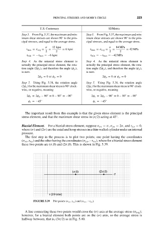
Biaxial Element. For a biaxial stress element, suppose σ xx = σ, σ yy = 2σ, and τ xy = 0,
where (σ) and (2σ) are the axial and hoop stresses in a thin-walled cylinder under an internal
pressure.
The first step in the process is to plot two points; one point having the coordinates
(σ xx ,τ xy ) and the other having the coordinates (σ yy ,−τ xy ), where for a biaxial stress element
these two points are (σ,0) and (2σ,0). This is shown in Fig. 5.39.
(s,0) (2s,0)
s
t (2q ccw)
FIGURE 5.39 Plot points (σ xx , t xy ) and (σ xx , −t xy ).
A line connecting these two points would cross the (σ) axis at the average stress (σ avg );
however, for a biaxial element both points are on the (σ) axis, so the average stress is
halfway between, that is, (3σ/2) as in Fig. 5.40.