
Page 240 - Marks Calculation for Machine Design
P. 240
P1: Shibu/Sanjay
14:35
January 4, 2005
Brown.cls
Brown˙C05
222
(s/2) STRENGTH OF MACHINES
(0,0) (s/2) (s,0)
s
s
s 2 1
(s/2)
(s/2) 2f = -90∞
s
t (2q ccw)
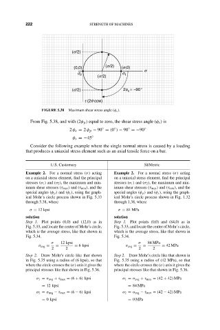
FIGURE 5.38 Maximum shear stress angle (φ s ).
From Fig. 5.38, and with (2φ p ) equal to zero, the shear stress angle (φ s ) is
2 φ s = 2 φ p − 90 = (0 ) − 90 =−90 ◦
◦
◦
◦
φ s =−45 ◦
Consider the following example where the single normal stress is caused by a loading
that produces a uniaxial stress element such as an axial tensile force on a bar.
U.S. Customary SI/Metric
Example 2. For a normal stress (σ) acting Example 2. For a normal stress (σ) acting
on a uniaxial stress element, find the principal on a uniaxial stress element, find the principal
stresses (σ 1 ) and (σ 2 ), the maximum and min- stresses (σ 1 ) and (σ 2 ), the maximum and min-
imum shear stresses (τ max ) and (τ min ), and the imum shear stresses (τ max ) and (τ min ), and the
special angles (φ p ) and (φ s ), using the graph- special angles (φ p ) and (φ s ), using the graph-
ical Mohr’s circle process shown in Fig. 5.33 ical Mohr’s circle process shown in Fig. 1.32
through 5.38, where through 1.38, where
σ = 12 kpsi σ = 84 MPa
solution solution
Step 1. Plot points (0,0) and (12,0) as in Step 1. Plot points (0,0) and (84,0) as in
Fig. 5.33, and locate the center of Mohr’s circle, Fig. 5.33, and locate the center of Mohr’s circle,
which is the average stress, like that shown in which is the average stress, like that shown in
Fig. 5.34. Fig. 5.34.
σ 12 kpsi σ 84 MPa
σ avg = = = 6 kpsi σ avg = = = 42 MPa
2 2 2 2
Step 2. Draw Mohr’s circle like that shown Step 2. Draw Mohr’s circle like that shown in
in Fig. 5.35 using a radius of (6 kpsi), so that Fig. 5.35 using a radius of (42 MPa), so that
where the circle crosses the (σ) axis it gives the where the circle crosses the (σ) axis it gives the
principal stresses like that shown in Fig. 5.36. principal stresses like that shown in Fig. 5.36.
σ 1 = σ avg + τ max = (6 + 6) kpsi σ 1 = σ avg + τ max = (42 + 42) MPa
= 12 kpsi = 84 MPa
σ 2 = σ avg − τ max = (6 − 6) kpsi σ 2 = σ avg − τ max = (42 − 42) MPa
= 0 kpsi = 0MPa