
Page 245 - Marks Calculation for Machine Design
P. 245
P1: Shibu/Sanjay
14:35
January 4, 2005
Brown.cls
Brown˙C05
PRINCIPAL STRESSES AND MOHR’S CIRCLE
The important result from this example is that the given stress element is the principal
◦
stress element, and that the maximum shear stress is (σ/2) acting at 45 . 227
Consider now the last of the three special elements, the pure shear element.
Pure Shear Element. For a pure shear stress element, suppose σ xx = 0, σ yy = 0, and
τ xy = τ, where (τ) is a known stress caused by either a single loading or a combination of
loadings.
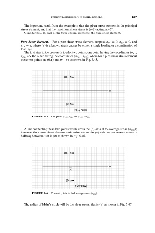
The first step in the process is to plot two points; one point having the coordinates (σ xx ,
τ xy ) and the other having the coordinates (σ yy ,−τ xy ), where for a pure shear stress element
these two points are (0,τ) and (0,−τ) as shown in Fig. 5.45.
(0,–t)
s
(0,t)
t (2q ccw)
FIGURE 5.45 Plot points (σ xx , t xy ) and (σ xx , −t xy ).
A line connecting these two points would cross the (σ) axis at the average stress (σ avg );
however, for a pure shear element both points are on the (τ) axis, so the average stress is
halfway between, that is (0) as shown in Fig. 5.46.
(0,–t)
s
(0)
(0,t)
t (2q ccw)
FIGURE 5.46 Connect points to find average stress (σ avg ).
The radius of Mohr’s circle will be the shear stress, that is (τ) as shown in Fig. 5.47.