
Page 247 - Marks Calculation for Machine Design
P. 247
P1: Shibu/Sanjay
14:35
January 4, 2005
Brown˙C05
Brown.cls
229
PRINCIPAL STRESSES AND MOHR’S CIRCLE
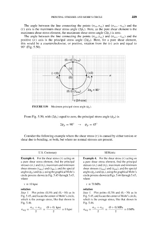
The angle between the line connecting the points (σ xx ,τ xy ) and (σ xx ,−τ xy ) and the
(τ) axis is the maximum shear stress angle (2φ s ). Here, as the pure shear element is the
maximum shear stress element, the maximum shear stress angle (2φ s ) is zero.
The angle between the line connecting the points (σ xx ,τ xy ) and (σ xx ,−τ xy ) and the
positive (σ) axis is the principal stress angle (2φ p ). Here, for a pure shear element,
this would be a counterclockwise, or positive, rotation from the (τ) axis and equal to
90 (Fig. 5.50).
◦
(0,–t) (t min )
(t)
(–t,0) (t,0)
s
s 2 (0) s 1
2f = 90∞
(0,t) (t max ) p
t (2q ccw)
FIGURE 5.50 Maximum principal stress angle (φ p ).
From Fig. 5.50, with (2φ s ) equal to zero, the principal stress angle (φ p ) is
2φ p = 90 ◦ → φ p = 45 ◦
Consider the following example where the shear stress (τ) is caused by either torsion or
shear due to bending, or both, but where no normal stresses are present.
U.S. Customary SI/Metric
Example 4. For the shear stress (τ) acting on Example 4. For the shear stress (τ) acting on
a pure shear stress element, find the principal a pure shear stress element, find the principal
stresses (σ 1 ) and (σ 2 ), maximum and minimum stresses (σ 1 ) and (σ 2 ), maximum and minimum
shear stresses (τ max ) and (τ min ), and the special shear stresses (τ max ) and (τ min ), and the special
angles(φ p )and(φ s ),usingthegraphicalMohr’s angles(φ p )and(φ s ),usingthegraphicalMohr’s
circle process shown in Fig. 5.45 through 5.45, circle process shown in Figs. 5.44 through 5.45,
where where
τ = 10 kpsi τ = 70 MPa
solution solution
Step 1. Plot points (0,10) and (0,−10) as in Step 1. Plot points (0,70) and (0,−70) as in
Fig. 5.45, and locate the center of Mohr’s circle, Fig. 5.45, and locate the center of Mohr’s circle,
which is the average stress, like that shown in which is the average stress, like that shown in
Fig. 5.46. Fig. 5.46.
σ xx + σ yy (0 + 0) kpsi σ xx + σ yy (0 + 0) MPa
σ avg = = = 0 kpsi σ avg = = = 0MPa
2 2 2 2