
Page 248 - Marks Calculation for Machine Design
P. 248
P1: Shibu/Sanjay
January 4, 2005
Brown˙C05
Brown.cls
230
U.S. Customary 14:35 STRENGTH OF MACHINES SI/Metric
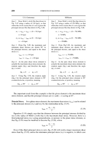
Step 2. Draw Mohr’s circle like that shown in Step 2. Draw Mohr’s circle like that shown in
Fig. 5.47 using a radius of (10 kpsi), so that Fig. 5.47 using a radius of (70 MPa), so that
where the circle crosses the (σ) axis it gives the where the circle crosses the (σ) axis it gives the
principal stresses like that shown in Fig. 5.48. principal stresses like that shown in Fig. 5.48.
σ 1 = σ avg + τ max = (0 + 10) kpsi σ 1 = σ avg + τ max = (0 + 70) MPa
= 10 kpsi = 70 MPa
σ 2 = σ avg − τ max = (0 − 10) kpsi σ 2 = σ avg − τ max = (0 − 70) MPa
=−10 kpsi =−70 MPa
Step 3. From Fig. 5.49, the maximum and Step 3. From Fig.5.49, the maximum and
minimum shear stresses are shown 90 ◦ to minimum shear stresses are shown 90 ◦ to
the principal stresses, and equal to the shear the principal stresses, and equal to the shear
stress (τ). stress (τ).
τ max = τ = 10 kpsi τ max = τ = 70 MPa
τ min =−τ max =−10 kpsi τ min =−τ max =−70 MPa
Step 4. As the pure shear stress element is Step 4. As the pure shear stress element is
actually the maximum shear stress element, the actually the maximum shear stress element, the
rotation angle (2φ s ) and therefore the angle rotation angle (2φ s ) and therefore the angle
(φ s ), is zero. (φ s ), is zero.
2φ s = 0 → φ s = 0 2φ s = 0 → φ s = 0
Step 5. Using Fig. 5.50, the rotation angle Step 5. Using Fig. 5.50, the rotation angle
(2φ p ) for the principal stress element is 90 ◦ (2φ p ) for the principal stress element is 90 ◦
counterclockwise, or positive, meaning counterclockwise, or positive, meaning
2φ p = 90 ◦ → φ p = 45 ◦ 2φ p = 90 ◦ → φ p = 45 ◦
The important result from this example is that the given element is the maximum shear
stress element, and that the principal stresses are (τ) and (−τ) acting at 45 .
◦
Triaxial Stress. For a plane stress element, the maximum shear stress (τ max ) can be related
to the principal stresses (σ 1 ) and (σ 2 ) by the relationship in Eq. (5.19).
σ 1 − σ 2
τ max = (5.19)
2
Equation (5.19) simply says that the distance between the principal stresses divided by
two is the radius of Mohr’s circle that is the maximum shear stress. However, there is a
third principal stress (σ 3 ) acting perpendicular, or normal, to the plane stress element, so
that Eq. (5.19) must be modified to become Eq. (5.20), where
σ 1 − σ 3
τ max = (5.20)
2
Even if this third principal stress is zero, Eq. (5.20) will yield a larger maximum shear
stress than Eq. (5.19), unless the minimum principal stress (σ 2 ) is negative, in which case