
Page 253 - Marks Calculation for Machine Design
P. 253
P1: Shibu
January 4, 2005
14:56
Brown.cls
Brown˙C06
STATIC DESIGN AND COLUMN BUCKLING
s 2 235
S y
II I
s 1
–S y S y
III IV
–S y
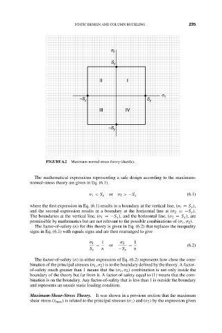
FIGURE 6.2 Maximum-normal-stress theory (ductile).
The mathematical expressions representing a safe design according to the maximum-
normal-stress theory are given in Eq. (6.1).
σ 1 < S y or σ 2 > −S y (6.1)
where the first expression in Eq. (6.1) results in a boundary at the vertical line, (σ 1 = S y ),
and the second expression results in a boundary at the horizontal line at (σ 2 =−S y ).
The boundaries at the vertical line, (σ 1 =−S y ), and the horizontal line, (σ 2 = S y ), are
permissible by mathematics but are not relevant to the possible combinations of (σ 1 , σ 2 ).
The factor-of-safety (n) for this theory is given in Eq. (6.2) that replaces the inequality
signs in Eq. (6.1) with equals signs and are then rearranged to give
σ 1 1 σ 2 1
= or = (6.2)
S y n −S y n
The factor-of-safety (n) in either expression of Eq. (6.2) represents how close the com-
bination of the principal stresses (σ 1 , σ 2 ) is to the boundary defined by the theory. A factor-
of-safety much greater than 1 means that the (σ 1 , σ 2 ) combination is not only inside the
boundary of the theory but far from it. A factor-of-safety equal to (1) means that the com-
bination is on the boundary. Any factor-of-safety that is less than 1 is outside the boundary
and represents an unsafe static loading condition.
Maximum-Shear-Stress Theory. It was shown in a previous section that the maximum
shear stress (τ max ) is related to the principal stresses (σ 1 ) and (σ 2 ) by the expression given