Page 258 - Marks Calculation for Machine Design
P. 258

P1: Shibu
                          January 4, 2005
                                      14:56
        Brown.cls
                 Brown˙C06
                                           STRENGTH OF MACHINES
                  240
                                                      Biaxial where
                                                           2
                                                      s 1  = s  > 0
                                                s 2
                                                S y
                             Boundary of allowable
                                combinations
                                                                 Biaxial where
                                                                 s  = 2s  > 0
                                                                       2
                                                                  1
                                                                      s 1
                                   –S y                       S y
                                                                Uniaxial where
                                                                s  > 0, s  = 0
                                                                 1
                                                                       2
                                               –S y
                                                    Pure shear where
                                                    s  > 0, s  = –s 1
                                                     1
                                                          2
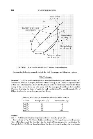
                         FIGURE 6.7  Load lines for uniaxial, biaxial, and pure shear combinations.
                    Consider the following example in both the U.S. Customary and SI/metric systems.

                                             U.S. Customary
                  Example 1. Plot the combinations given in the table below of the principal stresses (σ 1 , σ 2 )
                  from several selected examples presented earlier in Chap. 5, on a static design coordinate
                  system for ductile materials. Show the boundaries of the recommended theories for deter-
                  mining if the combinations are safe, along with the four special load lines shown in Fig.
                  6.7. Also, determine the factor-of-safety for each combination. Use a yield strength (S y ) of
                  12 kpsi that is at the low end for magnesium alloys.


                             Summary of the principal stresses from selected examples (in kpsi)
                             Example     Principal stress (σ 1 )  Principal stress (σ 2 )
                              5(§5.2)         11                −4
                              2(§5.3)         12                  0
                              3(§5.3)         16                  8
                              4(§5.3)         10                −10


                  solution
                  Step 1. Plot the combinations of principal stresses from the given table.
                    This is shown in Fig. 6.8. Notice that the combination of principal stresses for Example 5
                  (Sec. 5.2) falls outside the boundary in the fourth (IV) quadrant, the combination for
                  Example 2 (Sec. 5.3) falls on the uniaxial load line directly on the boundary, the combination
   253   254   255   256   257   258   259   260   261   262   263