Page 259 - Marks Calculation for Machine Design
P. 259

P1: Shibu
                                      14:56
                          January 4, 2005
                 Brown˙C06
        Brown.cls
                                     STATIC DESIGN AND COLUMN BUCKLING
                                           s 2                                    241
                           Boundary of allowable                    Biaxial where
                                                                    s  = s  > 0
                              combinations                    3      1  2
                                          12
                                                                    Biaxial where
                                                                    s  = 2s  > 0
                                                                     1
                                                                          2
                                                             2
                               –12
                                                                  s 1
                                                         12
                                                                  Uniaxial where
                                                                     > 0, s  = 0
                                                                  s 1
                                                           5            2
                                                             4
                                              –12
                                               Pure shear where
                                               s  > 0, s  = –s 1
                                                     2
                                                1
                                                              Scale: 1 kpsi ¥ 1 kpsi
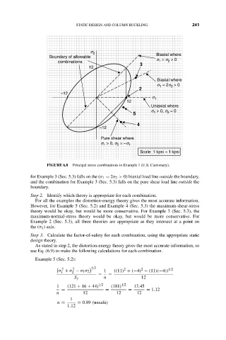
                          FIGURE 6.8  Principal stress combinations in Example 1 (U.S. Customary).
                    for Example 3 (Sec. 5.3) falls on the (σ 1 = 2σ 2 > 0) biaxial load line outside the boundary,
                    and the combination for Example 3 (Sec. 5.3) falls on the pure shear load line outside the
                    boundary.
                    Step 2. Identify which theory is appropriate for each combination.
                      For all the examples the distortion-energy theory gives the most accurate information.
                    However, for Example 5 (Sec. 5.2) and Example 4 (Sec. 5.3) the maximum-shear-stress
                    theory would be okay, but would be more conservative. For Example 3 (Sec. 5.3), the
                    maximum-normal-stress theory would be okay, but would be more conservative. For
                    Example 2 (Sec. 5.3), all three theories are appropriate as they intersect at a point on
                    the (σ 1 ) axis.
                    Step 3. Calculate the factor-of-safety for each combination, using the appropriate static
                    design theory.
                      As stated in step 2, the distortion-energy theory gives the most accurate information, so
                    use Eq. (6.9) to make the following calculations for each combination.
                      Example 5 (Sec. 5.2):
                                            1/2
                                2   2                   2     2          1/2

                               σ + σ − σ 1 σ 2  1   ((11) + (−4) − (11)(−4))
                                1   2
                                              =   =
                                     S y        n             12
                              1   (121 + 16 + 44) 1/2  (181) 1/2  13.45
                                =                =       =      = 1.12
                              n         12           12      12
                                   1
                              n =     = 0.89 (unsafe)
                                  1.12
   254   255   256   257   258   259   260   261   262   263   264