
Page 252 - Marks Calculation for Machine Design
P. 252
P1: Shibu
14:56
January 4, 2005
Brown.cls
Brown˙C06
STRENGTH OF MACHINES
234
s 2
S ut Brittle
Ductile
S y
II I
s 1
–S uc –S y S y S ut
III –S y IV
Ductile
Brittle
–S uc
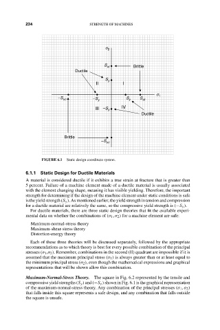
FIGURE 6.1 Static design coordinate system.
6.1.1 Static Design for Ductile Materials
A material is considered ductile if it exhibits a true strain at fracture that is greater than
5 percent. Failure of a machine element made of a ductile material is usually associated
with the element changing shape, meaning it has visible yielding. Therefore, the important
strength for determining if the design of the machine element under static conditions is safe
is the yield strength (S y ). As mentioned earlier, the yield strength in tension and compression
for a ductile material are relatively the same, so the compressive yield strength is (−S y ).
For ductile materials, there are three static design theories that fit the available experi-
mental data on whether the combinations of (σ 1 , σ 2 ) for a machine element are safe:
Maximum-normal-stress theory
Maximum-shear-stress theory
Distortion-energy theory
Each of these three theories will be discussed separately, followed by the appropriate
recommendations as to which theory is best for every possible combination of the principal
stresses (σ 1 ,σ 2 ). Remember, combinations in the second (II) quadrant are impossible if it is
assumed that the maximum principal stress (σ 1 ) is always greater than or at least equal to
the minimum principal stress (σ 2 ), even though the mathematical expressions and graphical
representations that will be shown allow this combination.
Maximum-Normal-Stress Theory. The square in Fig. 6.2 represented by the tensile and
compressive yield strengths (S y ) and (−S y ) shown in Fig. 6.1 is the graphical representation
of the maximum-normal-stress theory. Any combination of the principal stresses (σ 1 , σ 2 )
that falls inside this square represents a safe design, and any combination that falls outside
the square is unsafe.