
Page 246 - Marks Calculation for Machine Design
P. 246
P1: Shibu/Sanjay
January 4, 2005
14:35
Brown.cls
Brown˙C05
228
STRENGTH OF MACHINES
(0,–t)
Radius
(–t,0) (t,0)
s
(0)
(0,t)
t (2q ccw)
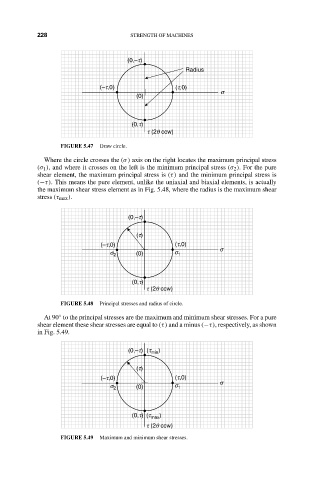
FIGURE 5.47 Draw circle.
Where the circle crosses the (σ) axis on the right locates the maximum principal stress
(σ 1 ), and where it crosses on the left is the minimum principal stress (σ 2 ). For the pure
shear element, the maximum principal stress is (τ) and the minimum principal stress is
(−τ). This means the pure element, unlike the uniaxial and biaxial elements, is actually
the maximum shear stress element as in Fig. 5.48, where the radius is the maximum shear
stress (τ max ).
(0,–t)
(t)
(–t,0) (t,0)
s
s 2 (0) s 1
(0,t)
t (2q ccw)
FIGURE 5.48 Principal stresses and radius of circle.
At 90 to the principal stresses are the maximum and minimum shear stresses. For a pure
◦
shear element these shear stresses are equal to (τ) and a minus (−τ), respectively, as shown
in Fig. 5.49.
(0,–t) (t min )
(t)
(–t,0) (t,0)
s
s 2 (0) s 1
(0,t) (t max )
t (2q ccw)
FIGURE 5.49 Maximum and minimum shear stresses.