
Page 301 - Mastering SolidWorks
P. 301
|
Selecting a SPecialty Feature 273
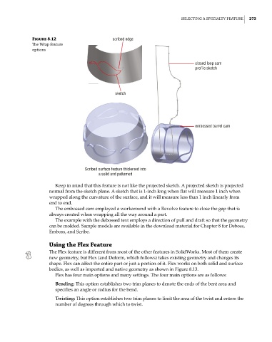
Figure 8.12 scribed edge
The Wrap feature
options
closed loop cam
profile sketch
sketch
embossed barrel cam
Scribed surface feature thickened into
a solid and patterned
Keep in mind that this feature is not like the projected sketch. A projected sketch is projected
normal from the sketch plane. A sketch that is 1-inch long when flat will measure 1 inch when
wrapped along the curvature of the surface, and it will measure less than 1 inch linearly from
end to end.
The embossed cam employed a workaround with a Revolve feature to close the gap that is
always created when wrapping all the way around a part.
The example with the debossed text employs a direction of pull and draft so that the geometry
can be molded. Sample models are available in the download material for Chapter 8 for Deboss,
Emboss, and Scribe.
Using the Flex Feature
The Flex feature is different from most of the other features in SolidWorks. Most of them create
new geometry, but Flex (and Deform, which follows) takes existing geometry and changes its
shape. Flex can affect the entire part or just a portion of it. Flex works on both solid and surface
bodies, as well as imported and native geometry as shown in Figure 8.13.
Flex has four main options and many settings. The four main options are as follows:
Bending: This option establishes two trim planes to denote the ends of the bent area and
specifies an angle or radius for the bend.
Twisting: This option establishes two trim planes to limit the area of the twist and enters the
number of degrees through which to twist.