
Page 199 - Materials Science and Engineering An Introduction
P. 199
6.2 Concepts of Stress and Strain • 171
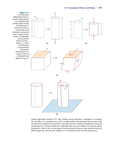
Figure 6.1 F
(a) Schematic
illustration of how a A 0
tensile load produces A 0 F
an elongation and
positive linear strain.
(b) Schematic il-
lustration of how a l l
compressive load 0 l 0 l
produces contraction
and a negative linear
strain. (c) Schematic
representation F
of shear strain g,
where g tan u. (a) F (b)
(d) Schematic
representation
of torsional A 0 A 0
deformation (i.e.,
angle of twist f)
produced by an F
applied torque T.
F
F
(c)
T
T
(d)
testing apparatus (Figure 6.3). The tensile testing machine is designed to elongate
the specimen at a constant rate, and to continuously and simultaneously measure the
instantaneous applied load (with a load cell) and the resulting elongations (using an
extensometer). A stress–strain test typically takes several minutes to perform and is
destructive; that is, the test specimen is permanently deformed and usually fractured.
[Photograph (a) opening this chapter is of a modern tensile-testing apparatus.]