
Page 201 - Materials Science and Engineering An Introduction
P. 201
6.2 Concepts of Stress and Strain • 173
Compression Tests 3
Compression stress–strain tests may be conducted if in-service forces are of this
type. A compression test is conducted in a manner similar to the tensile test, except
that the force is compressive and the specimen contracts along the direction of the
stress. Equations 6.1 and 6.2 are utilized to compute compressive stress and strain,
respectively. By convention, a compressive force is taken to be negative, which yields
a negative stress. Furthermore, because l 0 is greater than l i , compressive strains com-
puted from Equation 6.2 are necessarily also negative. Tensile tests are more com-
mon because they are easier to perform; also, for most materials used in structural
applications, very little additional information is obtained from compressive tests.
Compressive tests are used when a material’s behavior under large and permanent
(i.e., plastic) strains is desired, as in manufacturing applications, or when the material
is brittle in tension.
Shear and Torsional Tests 4
For tests performed using a pure shear force as shown in Figure 6.1c, the shear stress t
is computed according to
Definition of shear
stress
F
t = (6.3)
A 0
where F is the load or force imposed parallel to the upper and lower faces, each of which
has an area of A 0 . The shear strain g is defined as the tangent of the strain angle u, as
indicated in the figure. The units for shear stress and strain are the same as for their
tensile counterparts.
Torsion is a variation of pure shear in which a structural member is twisted in the
p manner of Figure 6.1d; torsional forces produce a rotational motion about the longitu-
dinal axis of one end of the member relative to the other end. Examples of torsion are
found for machine axles and drive shafts as well as for twist drills. Torsional tests are
normally performed on cylindrical solid shafts or tubes. A shear stress t is a function
of the applied torque T, whereas shear strain g is related to the angle of twist, f in
p Figure 6.1d.
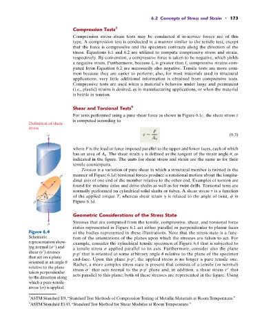
Geometric Considerations of the Stress State
Stresses that are computed from the tensile, compressive, shear, and torsional force
states represented in Figure 6.1 act either parallel or perpendicular to planar faces
Figure 6.4 of the bodies represented in these illustrations. Note that the stress state is a func-
Schematic tion of the orientations of the planes upon which the stresses are taken to act. For
representation show- example, consider the cylindrical tensile specimen of Figure 6.4 that is subjected to
ing normal (s ) and a tensile stress s applied parallel to its axis. Furthermore, consider also the plane
shear (t¿) stresses p-p¿ that is oriented at some arbitrary angle u relative to the plane of the specimen
that act on a plane end-face. Upon this plane p-p¿, the applied stress is no longer a pure tensile one.
oriented at an angle u Rather, a more complex stress state is present that consists of a tensile (or normal)
relative to the plane stress s that acts normal to the p-p¿ plane and, in addition, a shear stress t that
taken perpendicular
to the direction along acts parallel to this plane; both of these stresses are represented in the figure. Using
which a pure tensile
stress (s) is applied.
3 ASTM Standard E9, “Standard Test Methods of Compression Testing of Metallic Materials at Room Temperature.”
4 ASTM Standard E143, “Standard Test Method for Shear Modulus at Room Temperature.”