
Page 216 - Materials Science and Engineering An Introduction
P. 216
188 • Chapter 6 / Mechanical Properties of Metals
true strain Furthermore, it is occasionally more convenient to represent strain as true strain P T ,
defined by
Definition of true P T = ln l i (6.16)
strain l 0
If no volume change occurs during deformation—that is, if
A i l i = A 0 l 0 (6.17)
—then true and engineering stress and strain are related according to
Conversion of
engineering stress s T = s(1 + P) (6.18a)
to true stress
Conversion of (6.18b)
engineering strain P T = ln (1 + P)
to true strain
Equations 6.18a and 6.18b are valid only to the onset of necking; beyond this point, true
stress and strain should be computed from actual load, cross-sectional area, and gauge
length measurements.
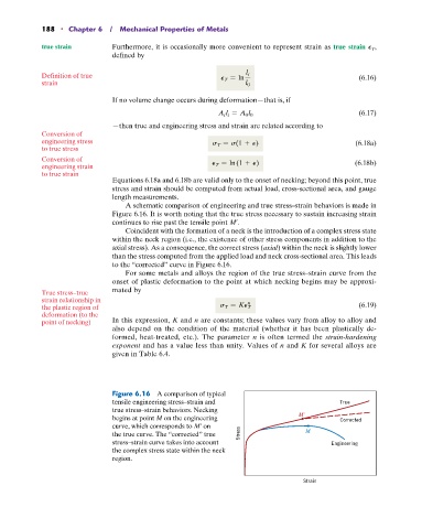
A schematic comparison of engineering and true stress–strain behaviors is made in
Figure 6.16. It is worth noting that the true stress necessary to sustain increasing strain
continues to rise past the tensile point M¿.
Coincident with the formation of a neck is the introduction of a complex stress state
within the neck region (i.e., the existence of other stress components in addition to the
axial stress). As a consequence, the correct stress (axial) within the neck is slightly lower
than the stress computed from the applied load and neck cross-sectional area. This leads
to the “corrected” curve in Figure 6.16.
For some metals and alloys the region of the true stress–strain curve from the
onset of plastic deformation to the point at which necking begins may be approxi-
True stress–true mated by
strain relationship in n
the plastic region of s T = KP T (6.19)
deformation (to the
point of necking) In this expression, K and n are constants; these values vary from alloy to alloy and
also depend on the condition of the material (whether it has been plastically de-
formed, heat-treated, etc.). The parameter n is often termed the strain-hardening
exponent and has a value less than unity. Values of n and K for several alloys are
given in Table 6.4.
Figure 6.16 A comparison of typical
tensile engineering stress–strain and True
true stress–strain behaviors. Necking
begins at point M on the engineering M Corrected
curve, which corresponds to M¿ on
the true curve. The “corrected” true Stress M
stress–strain curve takes into account Engineering
the complex stress state within the neck
region.
Strain