
Page 246 - Materials Science and Engineering An Introduction
P. 246
218 • Chapter 7 / Dislocations and Strengthening Mechanisms
7.2 BASIC CONCEPTS
Edge and screw are the two fundamental dislocation types. In an edge dislocation, local-
ized lattice distortion exists along the end of an extra half-plane of atoms, which also
defines the dislocation line (Figure 4.4). A screw dislocation may be thought of as result-
ing from shear distortion; its dislocation line passes through the center of a spiral, atomic
plane ramp (Figure 4.5). Many dislocations in crystalline materials have both edge and
screw components; these are mixed dislocations (Figure 4.6).
Plastic deformation corresponds to the motion of large numbers of dislocations.
An edge dislocation moves in response to a shear stress applied in a direction perpen-
dicular to its line; the mechanics of dislocation motion are represented in Figure 7.1.
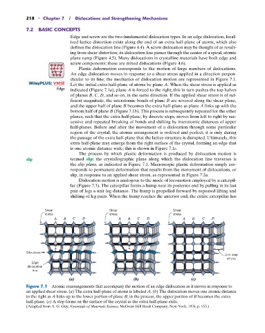
: VMSE Let the initial extra half-plane of atoms be plane A. When the shear stress is applied as
Edge indicated (Figure 7.1a), plane A is forced to the right; this in turn pushes the top halves
of planes B, C, D, and so on, in the same direction. If the applied shear stress is of suf-
ficient magnitude, the interatomic bonds of plane B are severed along the shear plane,
and the upper half of plane B becomes the extra half-plane as plane A links up with the
bottom half of plane B (Figure 7.1b). This process is subsequently repeated for the other
planes, such that the extra half-plane, by discrete steps, moves from left to right by suc-
cessive and repeated breaking of bonds and shifting by interatomic distances of upper
half-planes. Before and after the movement of a dislocation through some particular
region of the crystal, the atomic arrangement is ordered and perfect; it is only during
the passage of the extra half-plane that the lattice structure is disrupted. Ultimately, this
extra half-plane may emerge from the right surface of the crystal, forming an edge that
is one atomic distance wide; this is shown in Figure 7.1c.
The process by which plastic deformation is produced by dislocation motion is
slip termed slip; the crystallographic plane along which the dislocation line traverses is
the slip plane, as indicated in Figure 7.1. Macroscopic plastic deformation simply cor-
responds to permanent deformation that results from the movement of dislocations, or
slip, in response to an applied shear stress, as represented in Figure 7.2a.
Dislocation motion is analogous to the mode of locomotion employed by a caterpil-
lar (Figure 7.3). The caterpillar forms a hump near its posterior end by pulling in its last
pair of legs a unit leg distance. The hump is propelled forward by repeated lifting and
shifting of leg pairs. When the hump reaches the anterior end, the entire caterpillar has
Shear Shear Shear
stress stress stress
A B C D A B C D A B C D
Slip plane
Unit step
of slip
Edge
dislocation
line
(a) (b) (c)
Figure 7.1 Atomic rearrangements that accompany the motion of an edge dislocation as it moves in response to
an applied shear stress. (a) The extra half-plane of atoms is labeled A. (b) The dislocation moves one atomic distance
to the right as A links up to the lower portion of plane B; in the process, the upper portion of B becomes the extra
half-plane. (c) A step forms on the surface of the crystal as the extra half-plane exits.
(Adapted from A. G. Guy, Essentials of Materials Science, McGraw-Hill Book Company, New York, 1976, p. 153.)