Page 247 - Materials Science and Engineering An Introduction
P. 247

7.2 Basic Concepts  •  219


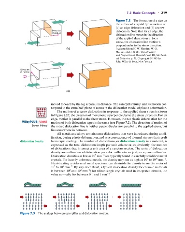
                                                                         Figure 7.2  The formation of a step on
                                                                         the surface of a crystal by the  motion of
                                                                         (a) an edge dislocation and (b) a screw
                                 Direction                               dislocation. Note that for an edge, the
                                 of motion
                                                                         dislocation line moves in the direction
                                                                         of the applied shear stress t; for a
                                                                         screw, the dislocation line motion is

                                                                         perpendicular to the stress direction.
                                          (a)                            (Adapted from H. W. Hayden, W. G.
                                                                         Moffatt, and J. Wulff, The Structure
                                                                         and Properties of Materials,Vol. III, Mechani-
                                                                         cal Behavior, p. 70. Copyright © 1965 by
                                                                         John Wiley & Sons, New York.)


              Direction
              of motion


                                          (b)


                                 moved forward by the leg separation distance. The caterpillar hump and its motion cor-
                                 respond to the extra half-plane of atoms in the dislocation model of plastic deformation.
                                    The motion of a screw dislocation in response to the applied shear stress is shown
                                 in Figure 7.2b; the direction of movement is perpendicular to the stress direction. For an
                                 edge, motion is parallel to the shear stress. However, the net plastic deformation for the
                          : VMSE  motion of both dislocation types is the same (see Figure 7.2). The direction of motion of
                     Screw, Mixed  the mixed dislocation line is neither perpendicular nor parallel to the applied stress, but
                                 lies somewhere in between.
                                    All metals and alloys contain some dislocations that were introduced during solidi-
                                 fication, during plastic deformation, and as a consequence of thermal stresses that result
              dislocation density  from rapid cooling. The number of dislocations, or dislocation density in a material, is
                                 expressed as the total dislocation length per unit volume or, equivalently, the number
                                 of dislocations that intersect a unit area of a random section. The units of dislocation
                                 density are millimeters of dislocation per cubic millimeter or just per square millimeter.
                                                            3
                                                                 2
                                 Dislocation densities as low as 10  mm  are typically found in carefully solidified metal
                                                                                                        2
                                                                                            9
                                                                                                  10
                                 crystals. For heavily deformed metals, the density may run as high as 10  to 10  mm .
                                 Heat-treating a deformed metal specimen can diminish the density to on the order of
                                             2
                                        6
                                   5
                                 10  to 10  mm . By way of contrast, a typical dislocation density for ceramic materials
                                                   4
                                            2
                                 is between 10  and 10  mm ; for silicon single crystals used in integrated circuits, the
                                                        2
                                                                     2
                                 value normally lies between 0.1 and 1 mm .


              Figure 7.3  The analogy between caterpillar and dislocation motion.
   242   243   244   245   246   247   248   249   250   251   252