
Page 249 - Materials Science and Engineering An Introduction
P. 249
7.4 Slip Systems • 221
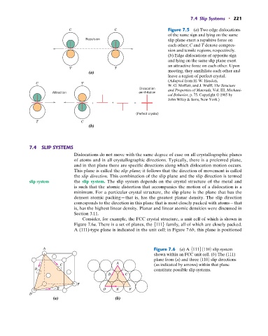
C C Figure 7.5 (a) Two edge dislocations
of the same sign and lying on the same
Repulsion slip plane exert a repulsive force on
each other; C and T denote compres-
sion and tensile regions, respectively.
(b) Edge dislocations of opposite sign
and lying on the same slip plane exert
an attractive force on each other. Upon
T T meeting, they annihilate each other and
(a)
leave a region of perfect crystal.
(Adapted from H. W. Hayden,
C T
W. G. Moffatt, and J. Wulff, The Structure
Dislocation and Properties of Materials, Vol. III, Mechani-
Attraction annihilation
cal Behavior, p. 75. Copyright © 1965 by
John Wiley & Sons, New York.)
; + =
(Perfect crystal)
T C
(b)
7.4 SLIP SYSTEMS
Dislocations do not move with the same degree of ease on all crystallographic planes
of atoms and in all crystallographic directions. Typically, there is a preferred plane,
and in that plane there are specific directions along which dislocation motion occurs.
This plane is called the slip plane; it follows that the direction of movement is called
the slip direction. This combination of the slip plane and the slip direction is termed
slip system the slip system. The slip system depends on the crystal structure of the metal and
is such that the atomic distortion that accompanies the motion of a dislocation is a
minimum. For a particular crystal structure, the slip plane is the plane that has the
densest atomic packing—that is, has the greatest planar density. The slip direction
corresponds to the direction in this plane that is most closely packed with atoms—that
is, has the highest linear density. Planar and linear atomic densities were discussed in
Section 3.11.
Consider, for example, the FCC crystal structure, a unit cell of which is shown in
Figure 7.6a. There is a set of planes, the 51116 family, all of which are closely packed.
A (111)-type plane is indicated in the unit cell; in Figure 7.6b, this plane is positioned
A Figure 7.6 (a) A 5111681109 slip system
shown within an FCC unit cell. (b) The (111)
plane from (a) and three 81109 slip directions
A
C (as indicated by arrows) within that plane
B constitute possible slip systems.
B C
F
E D E F
D
(a) (b)