
Page 252 - Materials Science and Engineering An Introduction
P. 252
224 • Chapter 7 / Dislocations and Strengthening Mechanisms
each relative to the stress axis (f and l angles) also differs. However, one slip system is
generally oriented most favorably—that is, has the largest resolved shear stress, t R (max):
t R (max) = s(cos f cos l) max (7.3)
In response to an applied tensile or compressive stress, slip in a single crystal commences on
the most favorably oriented slip system when the resolved shear stress reaches some critical
critical resolved value, termed the critical resolved shear stress t crss ; it represents the minimum shear stress
shear stress required to initiate slip and is a property of the material that determines when yielding
occurs. The single crystal plastically deforms or yields when t R (max) t crss , and the magni-
Yield strength of tude of the applied stress required to initiate yielding (i.e., the yield strength s y ) is
a single crystal—
dependence on the t crss
critical resolved s y = (7.4)
shear stress and the (cos f cos l) max
orientation of the
most favorably The minimum stress necessary to introduce yielding occurs when a single crystal is ori-
oriented slip system ented such that f = l = 45 ; under these conditions,
s y = 2t crss (7.5)
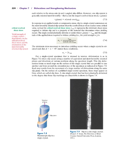
For a single-crystal specimen that is stressed in tension, deformation is as in
Figure 7.8, where slip occurs along a number of equivalent and most favorably oriented
planes and directions at various positions along the specimen length. This slip defor-
mation forms as small steps on the surface of the single crystal that are parallel to one
another and loop around the circumference of the specimen as indicated in Figure 7.8.
Each step results from the movement of a large number of dislocations along the same
slip plane. On the surface of a polished single-crystal specimen, these steps appear as
lines, which are called slip lines. A zinc single crystal that has been plastically deformed
to the degree that these slip markings are discernible is shown in Figure 7.9.
Direction
of force
Slip plane
Figure 7.9 Slip in a zinc single crystal.
Figure 7.8 (From C. F. Elam, The Distortion of Metal
Macroscopic slip in a Crystals, Oxford University Press, London,
single crystal. 1935.)