
Page 253 - Materials Science and Engineering An Introduction
P. 253
7.5 Slip in Single Crystals • 225
With continued extension of a single crystal, both the number of slip lines and the
slip step width increase. For FCC and BCC metals, slip may eventually begin along a
second slip system, the system that is next most favorably oriented with the tensile axis.
Furthermore, for HCP crystals having few slip systems, if the stress axis for the most
favorable slip system is either perpendicular to the slip direction (l 90 ) or parallel
to the slip plane (f 90 ), the critical resolved shear stress is zero. For these extreme
orientations, the crystal typically fractures rather than deforms plastically.
Concept Check 7.2 Explain the difference between resolved shear stress and critical
resolved shear stress.
[The answer may be found at www.wiley.com/college/callister (Student Companion Site).]
EXAMPLE PROBLEM 7.1
Resolved Shear Stress and Stress-to-Initiate-Yielding Computations
Consider a single crystal of BCC iron oriented such that a tensile stress is applied along a [010]
direction.
(a) Compute the resolved shear stress along a (110) plane and in a [111] direction when a ten-
sile stress of 52 MPa (7500 psi) is applied.
(b) If slip occurs on a (110) plane and in a [111] direction, and the critical resolved shear stress
is 30 MPa (4350 psi), calculate the magnitude of the applied tensile stress necessary to
initiate yielding.
Solution
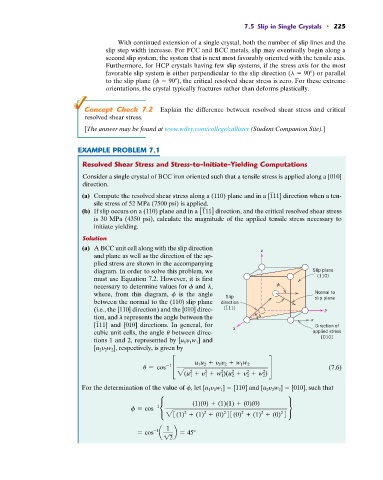
(a) A BCC unit cell along with the slip direction z
and plane as well as the direction of the ap-
plied stress are shown in the accompanying
diagram. In order to solve this problem, we Slip plane
must use Equation 7.2. However, it is first (110)
necessary to determine values for f and l,
where, from this diagram, f is the angle Slip Normal to
slip plane
between the normal to the (110) slip plane direction
(i.e., the [110] direction) and the [010] direc- [111] y
tion, and l represents the angle between the
[111] and [010] directions. In general, for x Direction of
cubic unit cells, the angle u between direc- applied stress
tions 1 and 2, represented by [u 1 y 1 w 1 ] and [010]
[u 2 y 2 w 2 ], respectively, is given by
-1
u = cos £ u 1 u 2 + y 1 y 2 + w 1 w 2 § (7.6)
2
2
2
2
2
2
2(u 1 + y 1 + w 1 )(u 2 + y 2 + w 2 )
For the determination of the value of f, let [u 1 y 1 w 1 ] [110] and [u 2 y 2 w 2 ] [010], such that
(1)(0) + (1)(1) + (0)(0)
f = cos -1 • ¶
2
2
2
2
2
2
23(1) + (1) + (0) 43(0) + (1) + (0) 4
1
-1
= cos a b = 45
12