
Page 251 - Materials Science and Engineering An Introduction
P. 251
7.5 Slip in Single Crystals • 223
Concept Check 7.1 Which of the following is the slip system for the simple cubic crystal
structure? Why?
5100681109
5110681109
5100680109
5110681119
(Note: A unit cell for the simple cubic crystal structure is shown in Figure 3.3.)
[The answer may be found at www.wiley.com/college/callister (Student Companion Site).]
7.5 SLIP IN SINGLE CRYSTALS
A further explanation of slip is simplified by treating the process in single crystals, then
making the appropriate extension to polycrystalline materials. As mentioned previ-
ously, edge, screw, and mixed dislocations move in response to shear stresses applied
along a slip plane and in a slip direction. As noted in Section 6.2, even though an applied
stress may be pure tensile (or compressive), shear components exist at all but parallel
or perpendicular alignments to the stress direction (Equation 6.4b). These are termed
resolved shear stress resolved shear stresses, and their magnitudes depend not only on the applied stress, but
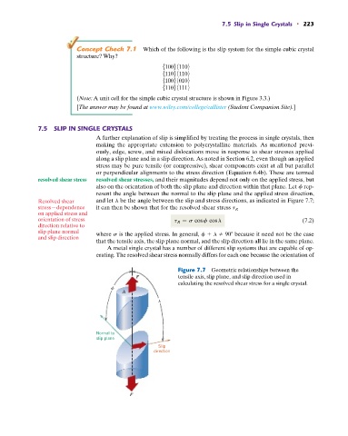
also on the orientation of both the slip plane and direction within that plane. Let f rep-
resent the angle between the normal to the slip plane and the applied stress direction,
Resolved shear and let l be the angle between the slip and stress directions, as indicated in Figure 7.7;
stress—dependence it can then be shown that for the resolved shear stress t R
on applied stress and
orientation of stress t R = s cos f cos l (7.2)
direction relative to
slip plane normal where s is the applied stress. In general, f l 90 because it need not be the case
and slip direction
that the tensile axis, the slip plane normal, and the slip direction all lie in the same plane.
A metal single crystal has a number of different slip systems that are capable of op-
erating. The resolved shear stress normally differs for each one because the orientation of
Figure 7.7 Geometric relationships between the
F tensile axis, slip plane, and slip direction used in
calculating the resolved shear stress for a single crystal.
A
Normal to
slip plane
Slip
direction
F