
Page 87 - Materials Chemistry, Second Edition
P. 87
74 2 Solid-State Chemistry
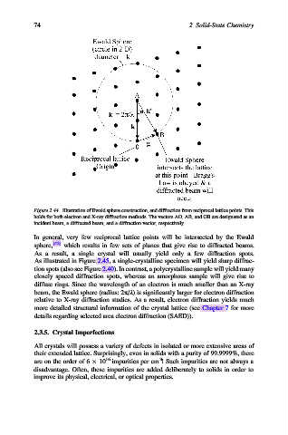
Figure 2.44. Illustration of Ewald sphere construction, and diffraction from reciprocal lattice points. This
holds for both electron and X-ray diffraction methods. The vectors AO, AB, and OB are designated as an
incident beam, a diffracted beam, and a diffraction vector, respectively.
In general, very few reciprocal lattice points will be intersected by the Ewald
sphere, [42] which results in few sets of planes that give rise to diffracted beams.
As a result, a single crystal will usually yield only a few diffraction spots.
As illustrated in Figure 2.45, a single-crystalline specimen will yield sharp diffrac-
tion spots (also see Figure 2.40). In contrast, a polycrystalline sample will yield many
closely spaced diffraction spots, whereas an amorphous sample will give rise to
diffuse rings. Since the wavelength of an electron is much smaller than an X-ray
beam, the Ewald sphere (radius: 2p/l) is significantly larger for electron diffraction
relative to X-ray diffraction studies. As a result, electron diffraction yields much
more detailed structural information of the crystal lattice (see Chapter 7 for more
details regarding selected area electron diffraction (SAED)).
2.3.5. Crystal Imperfections
All crystals will possess a variety of defects in isolated or more extensive areas of
their extended lattice. Surprisingly, even in solids with a purity of 99.9999%, there
3
are on the order of 6 10 16 impurities per cm ! Such impurities are not always a
disadvantage. Often, these impurities are added deliberately to solids in order to
improve its physical, electrical, or optical properties.