
Page 186 - Mathematical Models and Algorithms for Power System Optimization
P. 186
Discrete Optimization for Reactive Power Planning 177
6.4.2 Multistate Model for Discrete VAR Optimization
6.4.2.1 Description of the problem
In this section, the VAR optimization problem aims to study the allocation of capacitors under
multistate conditions. The objective function is to minimize cost of the new installed capacitors,
and the constraint condition includes the cost constraint and the multistate operation constraint,
which are described as follows:
(1) Objective: to decide the location and capacity of newly installed capacitors, so as to meet
system operation constraint under all states and minimize total investment in capacitors. The
key to this section is discrete optimization algorithm. Thus, for the objective function, only
investment cost of capacitors is considered, while capacitor operational cost will be ignored.
(2) Investment cost constraint: investment cost of capacitor includes two aspects: fixed cost
and variable cost. Definition of the cost is the same as that specified in Section 6.3.
1. Power system operation constraint: power system operation constraint consists of
several aspects below:
2. Generation and load balancing constraint under given load conditions, that is, power
flow balancing constraint between generation and load; under a multistate condition,
one reactive power planning mode has to meet multistate power flow balance.
3. For multistate power flow solutions, generator node and load node shall be able to
meet their respective bound constraints.
4. For each state, transformer tap shall be able to meet the constraint of variation range.
Transformer tap is taken as continuously adjustable, so that transformer tap under
different states has different solutions.
5. For each state, generator reactive power generation shall meet its bound constraint.
The reactive power generation of generator is taken as continuously adjustable.
Generator reactive power generation under different states may have different
solutions.
6. For each state, the current of outage line should meet its bound constraint.
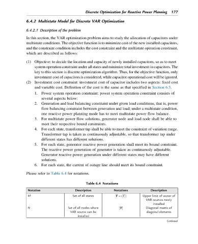
Please refer to Table 6.4 for notations.
Table 6.4 Notations
Notation Description Notations Description
M Set of all states Y ¼ Y i Upper limit of vector of
ðÞ
VAR sources newly
installed
N Set of all nodes where Y ½ Diagonal matrix of
VAR source can be diagonal elements
installed
Continued